





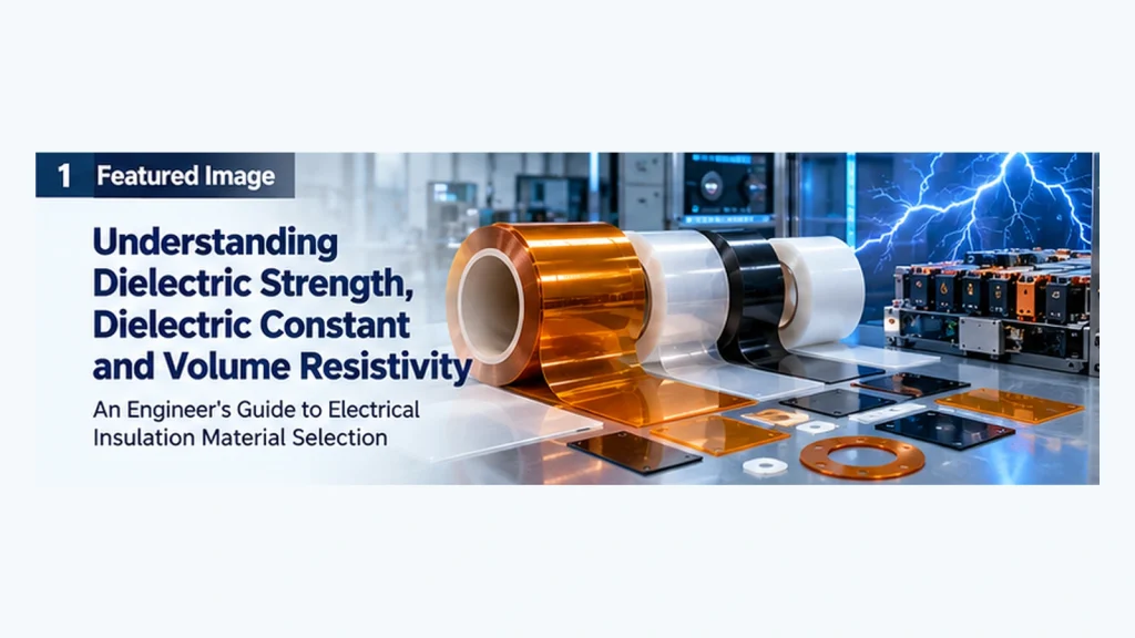
How to Interpret Electrical Insulation Film Properties, Compare Technical Datasheets and Select Materials for Real-World Applications
Selecting an electrical insulation film involves more than choosing a polymer with a high temperature rating or a high breakdown voltage.
For engineers designing battery modules, power electronics, PCB assemblies and industrial electrical equipment, three properties frequently appear in material technical datasheets:
- Dielectric strength
- Dielectric constant
- Volume resistivity
Although all three describe electrical behavior, they answer fundamentally different questions.
Dielectric strength indicates the electric field at which insulation breaks down under specified test conditions. Dielectric constant describes how a material responds to an electric field and influences capacitance. Volume resistivity describes resistance to electrical current flowing through the material’s bulk.
Confusing these properties can lead to incorrect material comparisons, unnecessary costs or insufficient design margins.
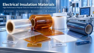
This guide explains their physical meanings, test methods, engineering limitations and practical implications for selecting polyimide (PI), polyester (PET), polyphenylene sulfide (PPS), polyethylene naphthalate (PEN) and polytetrafluoroethylene (PTFE) insulation films.
1. Why Electrical Properties Matter in Insulation Material Selection
Electrical insulation materials are used to separate conductive components and help maintain the intended electrical behavior of an assembly.
Common applications include:
- Battery cell and module insulation
- Busbar and terminal barriers
- Motor and transformer insulation
- Power inverter insulation
- PCB and electronic assembly insulation
- Semiconductor equipment components
- Industrial electrical equipment
However, different applications place different demands on the insulation material.
A battery module liner may require adequate dielectric withstand, dimensional stability and resistance to mechanical damage.
A high-frequency electronic substrate may require controlled relative permittivity and low dielectric loss.
A DC electrical barrier may require high insulation resistance over a defined temperature and humidity range.
These applications cannot be evaluated using one electrical property alone.
The correct insulation material is the one whose electrical, thermal, mechanical and processing characteristics meet the complete application requirements.
2. Three Key Electrical Properties: What Is the Difference?
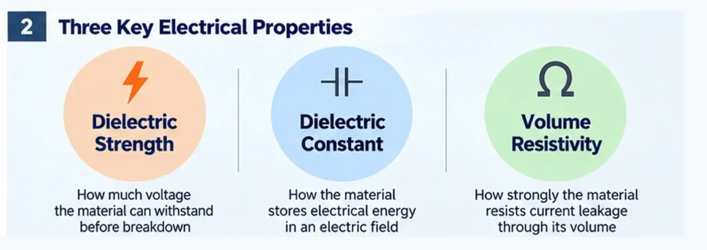
Dielectric strength, dielectric constant and volume resistivity should be interpreted as separate properties.
| Property | What It Describes | Common Unit | Main Engineering Question |
|---|---|---|---|
| Dielectric strength | Electric field at electrical breakdown | kV/mm or V/m | Can the insulation withstand the required electric stress? |
| Dielectric constant | Relative permittivity of a material | Dimensionless | How does the material affect capacitance and electric-field behavior? |
| Volume resistivity | Resistance to current flow through the material’s bulk | Ω·cm or Ω·m | How strongly does the material resist bulk leakage current? |
Three Properties, Three Different Failure or Design Concerns
Dielectric strength is primarily associated with breakdown under a specified test.
Dielectric constant is associated with polarization, capacitance and electromagnetic behavior.
Volume resistivity is associated with bulk conduction and leakage.
A film can have a relatively low dielectric constant while still providing useful electrical insulation.
Likewise, a material can have high volume resistivity without necessarily having the highest breakdown strength.
These values are not interchangeable.
3. Dielectric Strength: Understanding Electrical Breakdown
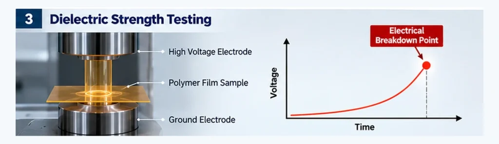
Dielectric strength describes the magnitude of the electric field at which a material undergoes electrical breakdown under defined test conditions.
It is commonly expressed in kilovolts per millimeter (kV/mm).
Basic Calculation
For a simple, approximately uniform electric field across a specimen:
Dielectric strength ≈ Breakdown voltage / Specimen thickness
For example, suppose a hypothetical 0.10 mm film breaks down at 8 kV in a particular test.
The calculated breakdown field is:
8 kV / 0.10 mm = 80 kV/mm
This is an illustrative calculation, not a specification for any particular polymer film.
Actual measurements depend on the test arrangement and conditions.
Why Dielectric Strength Is Important
Dielectric strength helps engineers evaluate whether an insulation material can withstand electrical stress without catastrophic breakdown.
It is relevant to:
- Electrical barriers between conductive parts
- Battery and busbar insulation
- Motor insulation systems
- Power electronics
- High-voltage equipment
However, the measured value should not be used directly as an allowable continuous operating electric field.
A practical design must account for the applicable safety standard, voltage transients, geometry, aging, environmental exposure and appropriate design margins.
Factors That Influence Dielectric Strength
1. Film thickness
Breakdown voltage generally changes with specimen thickness, but normalized dielectric strength does not necessarily remain constant across thicknesses.
Therefore, it is unsafe to assume that doubling film thickness always doubles the breakdown voltage.
2. Electrode geometry
Electrode shape, size and contact condition influence the electric-field distribution.
3. Temperature
Elevated temperature can change the electrical and mechanical behavior of polymer films.
4. Moisture and conditioning
Humidity, absorbed moisture and specimen conditioning may affect results.
5. Defects and contamination
Voids, inclusions, scratches and other defects can create local weaknesses.
6. Test voltage and duration
AC, DC and impulse tests may produce different breakdown behavior. Voltage ramp rate and exposure duration also matter.
Common Test Standards
Relevant standards include:
- ASTM D149 — Dielectric breakdown voltage and dielectric strength of solid electrical insulating materials at commercial power frequencies
- IEC 60243-1 — Electrical strength of insulating materials: Tests at power frequencies
Always review the edition, specimen preparation and actual test conditions specified in the report.
Engineering Note: Breakdown Strength vs Working Voltage
A dielectric strength value is not a complete insulation design approval.
For example, a film with an impressive laboratory breakdown result may still be unsuitable if the installed part has:
- Inadequate edge coverage
- Sharp conductive features
- Excessive mechanical stress
- Uncontrolled surface contamination
- Insufficient creepage or clearance
- Poor aging performance
For critical electrical systems, qualification should evaluate the final construction rather than relying solely on a material datasheet.
4. Dielectric Constant: Understanding Relative Permittivity
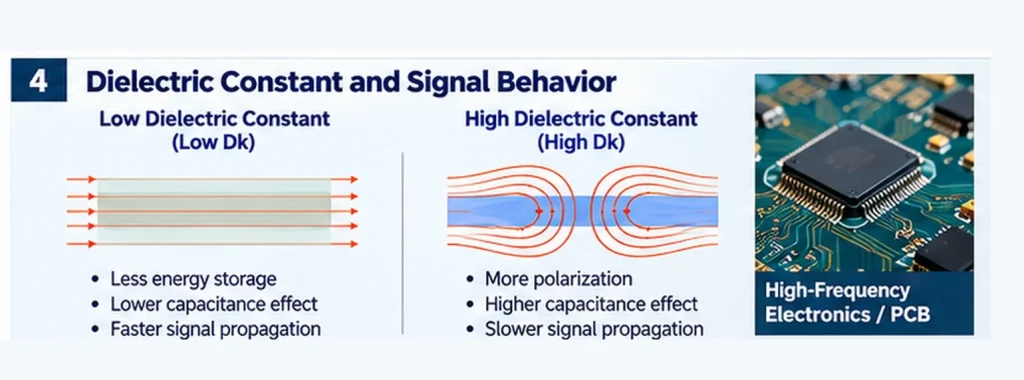
Dielectric constant is commonly used to describe a material’s relative permittivity, often written as εr or Dk.
It describes the relationship between the permittivity of a material and that of free space.
Unlike dielectric strength, dielectric constant is dimensionless.
How Dielectric Constant Affects Capacitance
For an ideal parallel-plate capacitor:
C = ε₀ × εr × A / d
Where:
- C = capacitance
- ε₀ = permittivity of free space
- εr = relative permittivity
- A = electrode area
- d = separation between electrodes
When geometry remains constant, a higher relative permittivity produces a higher capacitance in this simplified model.
Why Dielectric Constant Matters
Relative permittivity can influence:
- Capacitance
- Parasitic coupling
- Signal propagation
- Transmission-line impedance
- Electric-field distribution
- High-frequency circuit design
For some high-speed and RF applications, a lower Dk may be desirable.
However, lower dielectric constant is not automatically better for every application.
Some designs intentionally require higher capacitance or a particular impedance.
Frequency Dependence
A dielectric constant reported at 1 kHz should not automatically be treated as the value at 1 GHz.
The electrical response of polymer materials can vary with frequency and temperature.
For high-frequency applications, engineers should request data measured at the relevant operating frequency.
Dielectric Constant vs Dissipation Factor
Dielectric constant and dielectric loss are related but different.
The dissipation factor, often expressed as tan δ or Df, describes dielectric loss under an alternating electric field.
For signal-sensitive applications, both Dk and Df may be important.
A material with a low Dk does not necessarily have the lowest dielectric loss under all conditions.
Relevant Test Standards
Common references include:
- ASTM D150 — AC loss characteristics and permittivity of solid electrical insulation
- IEC 60250 — Permittivity and dielectric dissipation factor of electrical insulating materials at power, audio and radio frequencies
Test frequency, temperature, specimen thickness and measurement method should accompany reported values.
5. Volume Resistivity: Understanding Bulk Leakage Current
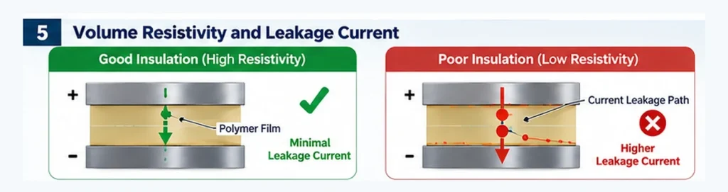
Volume resistivity describes how strongly a material resists electric current flowing through its volume.
It is commonly expressed in Ω·cm or Ω·m.
A higher volume resistivity generally indicates greater resistance to bulk electrical conduction under the stated test conditions.
Resistivity and Resistance Are Not the Same
For a uniform material in a simple geometry:
R = ρ × L / A
Where:
- R = electrical resistance
- ρ = volume resistivity
- L = conduction path length
- A = cross-sectional area
Resistance depends on both the material and specimen geometry.
Volume resistivity is a material property measured under defined conditions.
Why Volume Resistivity Matters
It is relevant when evaluating:
- DC insulation behavior
- Leakage current
- Electrical isolation
- Environmental stability
- Insulation performance at elevated temperature
For example, a film used as a barrier between conductive components may require low leakage under a specified DC voltage and operating temperature.
However, a room-temperature resistivity value alone does not establish long-term reliability.
Volume Resistivity vs Surface Resistivity
These properties must be distinguished.
Volume resistivity describes conduction through the bulk of a material.
Surface resistivity relates to conduction along the material surface.
Surface conduction can be strongly influenced by humidity, contamination and surface condition.
A film may have high bulk resistivity while its installed surface condition creates a different leakage risk.
Important Test Conditions
When comparing volume resistivity values, review:
- Applied voltage
- Electrification time
- Temperature
- Relative humidity
- Specimen conditioning
- Electrode arrangement
- Test method
For certain insulating polymers, current may change over time after voltage is applied because of polarization and absorption effects.
This makes measurement timing important.
Relevant Test Standards
Common references include:
- ASTM D257 — DC resistance or conductance of insulating materials
- IEC 60093 — Volume resistivity and surface resistivity of solid electrical insulating materials
Do not compare values from different methods as though they were measured under identical conditions.
6. How the Three Properties Work Together
Consider three hypothetical engineering applications.
Example A: Battery Module Insulation
An engineer is selecting a thin film to electrically separate conductive battery components.
The design may prioritize:
- Adequate dielectric withstand
- Insulation resistance
- Temperature exposure
- Mechanical protection
- Dimensional stability
- Flame-performance requirements, where applicable
Dielectric constant may be less important than dielectric withstand and physical durability in this application.
However, the exact requirements depend on the electrical and mechanical design.
Example B: High-Frequency Electronics
A designer is evaluating an insulating material close to a controlled-impedance signal path.
The design may prioritize:
- Relative permittivity at operating frequency
- Dissipation factor
- Thickness tolerance
- Dimensional stability
- Moisture sensitivity
In this case, Dk and Df may have a greater effect on circuit performance than a simple comparison of room-temperature volume resistivity.
Example C: Industrial DC Insulation Barrier
An engineer is selecting a film for long-term electrical isolation.
Important factors may include:
- Volume resistivity at service temperature
- Dielectric withstand
- Environmental exposure
- Mechanical stability
- Surface contamination
- Long-term aging
The correct evaluation involves both initial material properties and application-level testing.
7. Comparing PI, PET, PPS, PEN and PTFE Insulation Films
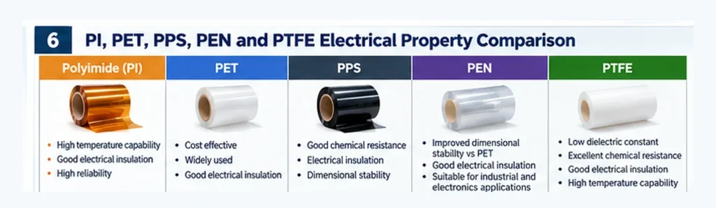
Polymer families provide useful starting points, but they should not be treated as fixed electrical-performance grades.
The same polymer family may contain films with different thicknesses, additives, orientation, surface treatments and processing histories.
| Material | Common Selection Considerations | Questions to Verify |
|---|---|---|
| PI | High-temperature electrical insulation in suitable grades | Dielectric strength at required thickness; thermal aging; dimensional stability |
| PET | Cost-effective, widely available insulation film | Temperature limit; breakdown data; shrinkage; flame classification if required |
| PPS | Thermal and chemical resistance in suitable grades | Film-grade electrical data; mechanical properties; process compatibility |
| PEN | Useful thermal and dimensional characteristics in selected grades | Frequency-dependent properties; MD/TD stability; actual grade availability |
| PTFE | Low relative permittivity in many grades; chemical resistance | Thickness, creep, bonding, mechanical behavior and test conditions |
Polyimide (PI) Film
Polyimide is widely considered for applications requiring electrical insulation at elevated temperatures.
Its properties make it relevant to motors, electronics and other demanding industrial applications.
However, PI grades can differ substantially.
Engineers should verify dielectric strength, resistivity, thermal exposure capability and mechanical behavior for the exact film grade.
For further comparison, read our PI vs PET Film Selection Guide.
PET Film
PET is widely used in electrical insulation because of its availability, processing versatility and cost-performance balance.
PET films can be supplied in different thicknesses and converted into sheets, rolls or custom die-cut parts.
For battery and industrial electrical applications, confirm the required temperature range and electrical properties.
If flame retardancy is required, review the exact grade and applicable certification rather than assuming that standard PET is flame-retardant.
PPS Film
PPS films may be considered for applications involving elevated temperatures or demanding chemical environments.
However, dielectric behavior depends on the exact film formulation and test conditions.
Do not assume that improved thermal capability automatically means higher dielectric strength or higher resistivity.
PEN Film
PEN may be considered when an application requires a different balance of thermal, dimensional and electrical properties than conventional PET.
Engineers should request grade-specific electrical and dimensional data, especially where temperature cycling or precision die-cutting is involved.
PTFE Film
PTFE is known for chemical resistance and relatively low dielectric constant in many grades.
It may be useful in selected high-frequency and industrial applications.
Nevertheless, creep, dimensional behavior, mechanical strength and adhesion can limit its suitability in certain assemblies.
A low dielectric constant does not eliminate the need for mechanical and thermal evaluation.
Is One Material Electrically Superior?
No single polymer should be described as the best electrical insulation material across every application.
Material selection should balance:
- Breakdown performance
- Leakage resistance
- Permittivity and dielectric loss
- Operating temperature
- Mechanical requirements
- Environmental conditions
- Thickness and dimensional tolerances
- Availability and converting requirements
8. How to Compare Electrical Properties in a Technical Datasheet
A technical datasheet is only useful when its values are interpreted correctly.
Check the Test Method
The reported value should identify the standard and, where relevant, the test configuration.
For example, dielectric strength reported using ASTM D149 should not automatically be treated as equivalent to a result from a different voltage waveform or electrode arrangement.
Check Specimen Thickness
Film thickness can influence measured breakdown behavior.
When comparing dielectric strength, check whether the values were measured on comparable thicknesses.
Check Frequency
Dielectric constant and dissipation factor can depend on frequency.
For high-frequency designs, request values at relevant frequencies rather than relying on a single low-frequency result.
Check Temperature and Humidity
Electrical properties may vary with temperature and environmental conditioning.
A result measured under standard laboratory conditions may not represent a hot, humid or chemically exposed installation.
Check Units
Common units include:
| Property | Unit | Conversion or Interpretation |
|---|---|---|
| Dielectric strength | kV/mm | 1 kV/mm = 1 MV/m |
| Relative permittivity | None | Dimensionless |
| Volume resistivity | Ω·cm | 1 Ω·m = 100 Ω·cm |
| Dissipation factor | None | Often reported as Df or tan δ |
Check Whether Data Is Typical or Guaranteed
A typical property value is not necessarily a guaranteed minimum or maximum.
For safety-critical designs, request the relevant specification limits and qualification documentation.
Check Material Grade and Traceability
The polymer name alone is not sufficient.
Specify the exact material grade, thickness, surface condition and any adhesive or coating.
Example: Two Datasheets That Should Not Be Compared Directly
Suppose:
- Film A: Dielectric strength measured on a 25 µm specimen using an AC test
- Film B: Breakdown voltage measured on a 125 µm specimen using a DC test
A direct numerical comparison may be misleading.
Before choosing a material, request comparable test conditions or conduct application-specific testing.
9. Application-Specific Electrical Insulation Requirements
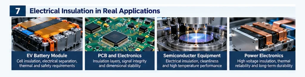
EV Battery and Energy Storage Systems
Battery insulation films may be used around cells, busbars, module structures and electrical connections.
Key considerations can include:
- Dielectric withstand
- Insulation resistance
- Temperature exposure
- Mechanical protection
- Dimensional accuracy
- Flame classification and supporting documentation, when specified
A film with high dielectric strength is not automatically approved for a battery application.
The complete component and applicable product requirements must be considered.
PCB and Electronics
In electronic assemblies, insulation films may function as protective barriers, flexible electrical insulation or temporary process materials.
The selection priorities depend on whether the material is part of a signal path, a protective barrier or a manufacturing process.
For high-frequency circuit structures, Dk and Df can be important.
For a simple protective barrier, dielectric withstand and dimensional stability may be more relevant.
Semiconductor Equipment
Semiconductor manufacturing equipment can involve elevated temperatures, precision components and demanding cleanliness requirements.
Electrical properties should be considered alongside:
- Thermal stability
- Outgassing or contamination requirements
- Chemical compatibility
- Dimensional stability
- Processing and handling requirements
Power Electronics and Inverters
Power electronics may expose insulation to high electric fields, temperature changes and mechanical constraints.
Engineers should evaluate:
- Dielectric withstand
- Insulation resistance
- Partial discharge behavior where applicable
- Thermal aging
- Mechanical and interface reliability
Material-level breakdown data alone cannot establish the performance of the final electrical insulation system.
10. Common Mistakes When Selecting Insulation Films
Mistake 1: Choosing the Highest Dielectric Strength
A high breakdown field does not guarantee the best performance in every electrical system.
Better approach: Define the actual voltage stress, geometry and qualification criteria.
Mistake 2: Treating Dielectric Constant as Insulation Strength
Dielectric constant does not indicate the electric field at which a material will break down.
Better approach: Evaluate Dk for capacitance and signal behavior, and dielectric strength for breakdown concerns.
Mistake 3: Confusing Volume Resistivity With Surface Resistivity
These measure different conduction paths.
Better approach: Determine whether the application is limited by bulk leakage, surface leakage or both.
Mistake 4: Comparing Datasheet Values Without Test Conditions
Values measured at different temperatures, frequencies or specimen thicknesses may not be directly comparable.
Better approach: Compare results under equivalent conditions.
Mistake 5: Ignoring Dielectric Loss
A low dielectric constant does not necessarily mean low dielectric loss.
Better approach: Review dissipation factor at the relevant frequency.
Mistake 6: Ignoring Mechanical and Thermal Requirements
Electrical insulation films can fail because of cracking, abrasion, deformation or loss of coverage.
Better approach: Qualify the complete assembly under representative service conditions.
Mistake 7: Assuming Every Grade of a Polymer Has the Same Properties
PI, PET, PPS, PEN and PTFE are polymer families, not single fixed specifications.
Better approach: Request data for the actual film grade and thickness.
11. Engineering Workflow for Insulation Material Selection
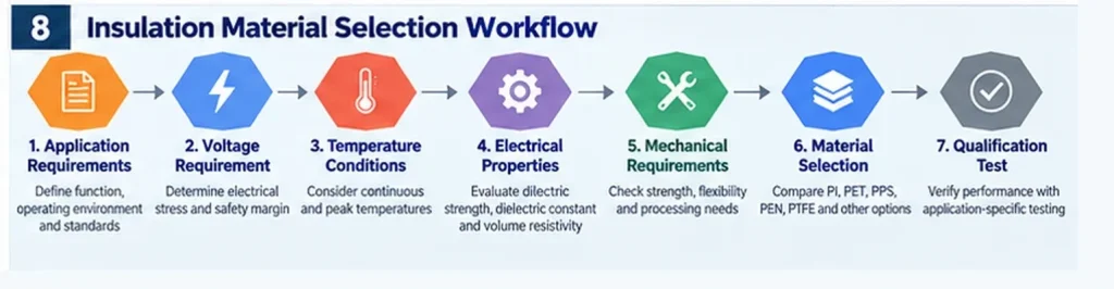
A practical material-selection process can follow seven steps.
Step 1: Define the Electrical Function
Determine whether the film provides:
- High-voltage isolation
- General electrical separation
- Controlled dielectric behavior
- Protective insulation
- Temporary process protection
Step 2: Define Voltage and Electric-Field Requirements
Identify:
- AC or DC voltage
- Normal operating voltage
- Transient or surge conditions
- Required withstand test
- Relevant safety standards
Step 3: Define Temperature and Environment
Specify:
- Continuous operating temperature
- Peak temperature
- Thermal cycling conditions
- Humidity
- Chemical exposure
- Expected service life
Step 4: Select the Relevant Electrical Properties
For breakdown concerns, prioritize dielectric withstand testing.
For signal behavior, evaluate Dk and Df.
For bulk leakage, evaluate volume resistivity and insulation resistance.
Step 5: Evaluate Geometry and Mechanical Requirements
Review:
- Film thickness
- Cutout dimensions
- Hole positioning
- Flexibility
- Abrasion
- Adhesive requirements
- Installation constraints
Step 6: Compare Material Grades
Shortlist suitable PI, PET, PPS, PEN or PTFE grades using comparable datasheet information.
Step 7: Validate the Final Construction
Conduct the applicable electrical, thermal, mechanical and environmental tests on representative specimens.
A successful material selection is based on the final application’s requirements—not a single favorable datasheet number.
12. RFQ Checklist for Electrical Insulation Films
When requesting material recommendations or quotations, provide:
| RFQ Item | Required Information |
|---|---|
| Application | Battery, PCB, inverter, motor or other equipment |
| Electrical function | Isolation, protective barrier, dielectric layer |
| Voltage | AC/DC, operating and transient conditions |
| Electrical tests | Dielectric withstand, resistance, Dk/Df if applicable |
| Temperature | Continuous, peak and cycling conditions |
| Film material | PI, PET, PPS, PEN, PTFE or open to recommendation |
| Thickness | Nominal value and tolerance |
| Format | Roll, sheet or die-cut part |
| Drawing | Dimensions, holes, radii and tolerances |
| Adhesive | Required chemistry, thickness and substrate |
| Environmental exposure | Humidity, chemicals, vibration and aging |
| Documentation | TDS, test reports and compliance requirements |
| Volume | Samples, annual quantity and delivery schedule |
Where required electrical test data is unavailable, samples and a qualification plan should be discussed before material approval.
13. Electrical Insulation Film and Custom Converting Support
HighTemp Material supports industrial customers sourcing high-temperature films and precision-converted electrical insulation components.
Our material portfolio includes:
- Polyimide (PI) film
- PET electrical insulation film
- PPS film
- PEN film
- PTFE film
- Selected adhesive-backed insulation materials
Available converting discussions include:
For application-specific requirements, our team can discuss material availability, thickness, dimensions, converting options and available technical documentation.
Request Material Selection Support
Are you selecting an insulation film for a battery, power electronics, PCB or industrial equipment project?
Send us your operating voltage, temperature range, material preference, thickness, drawing and expected quantity.
Contact HighTemp Material to discuss suitable material and converting options.
Frequently Asked Questions
1. What is the difference between dielectric strength and dielectric constant?
Dielectric strength describes the electric field at which breakdown occurs under specified conditions. Dielectric constant describes relative permittivity and affects capacitance and electric-field behavior.
2. What is the difference between dielectric strength and volume resistivity?
Dielectric strength concerns breakdown, while volume resistivity concerns resistance to bulk electrical conduction. A material’s performance in one property does not determine the other.
3. Is higher dielectric strength always better?
Not necessarily. The value must be considered alongside specimen thickness, test conditions, design geometry, operating environment and the application’s actual electrical requirements.
4. Is a lower dielectric constant always better?
No. Lower Dk can be useful in some high-frequency applications, but the correct value depends on the circuit design. Dissipation factor and frequency dependence are also important.
5. Which has better electrical insulation properties: PI or PET?
Both can provide useful electrical insulation. The better choice depends on the exact film grades, thickness, temperature, electrical requirements and mechanical conditions.
6. Does dielectric strength increase with film thickness?
Breakdown voltage often increases with thickness, but not necessarily in direct proportion. Normalized dielectric strength may vary with thickness and test conditions.
7. Why does volume resistivity change with temperature?
Electrical conduction mechanisms in polymer materials can be temperature-dependent. Actual behavior varies by material, grade, moisture content and test conditions.
8. What is the difference between volume resistivity and surface resistivity?
Volume resistivity describes bulk conduction through a material, while surface resistivity relates to conduction along its surface. Both may be relevant to electrical insulation design.
9. Which test standards should engineers review?
Common references include ASTM D149 and IEC 60243-1 for electrical strength, ASTM D150 and IEC 60250 for permittivity and dielectric loss, and ASTM D257 and IEC 60093 for resistivity.
10. Can a high dielectric strength film replace a thicker insulation layer?
Not automatically. Thickness selection depends on applicable electrical safety requirements, mechanical integrity, aging, geometry and validation of the final construction.
Conclusion
Dielectric strength, dielectric constant and volume resistivity are fundamental but distinct electrical properties.
Dielectric strength helps characterize breakdown behavior.
Dielectric constant helps characterize polarization, capacitance and electromagnetic performance.
Volume resistivity helps characterize resistance to bulk electrical leakage.
For PI, PET, PPS, PEN and PTFE films, these properties must be interpreted using the exact material grade, specimen thickness, test conditions and intended application.
The best insulation material is not necessarily the one with the highest value in a single datasheet column.
It is the material that satisfies the complete electrical, thermal, mechanical and manufacturing requirements of the final design.
Contact HighTemp Material for electrical insulation film and custom converting discussions.
Technical References
- ASTM D149 — Standard Test Method for Dielectric Breakdown Voltage and Dielectric Strength of Solid Electrical Insulating Materials at Commercial Power Frequencies
- ASTM D150 — Standard Test Methods for AC Loss Characteristics and Permittivity (Dielectric Constant) of Solid Electrical Insulation
- ASTM D257 — Standard Test Methods for DC Resistance or Conductance of Insulating Materials
- IEC 60243-1 — Electrical Strength of Insulating Materials: Tests at Power Frequencies
- IEC 60250 — Recommended Methods for the Determination of the Permittivity and Dielectric Dissipation Factor of Electrical Insulating Materials
- IEC 60093 — Methods of Test for Volume Resistivity and Surface Resistivity of Solid Electrical Insulating Materials
Engineering disclaimer: The explanations and example calculations in this article are for general material-selection guidance. They are not product-specific test results, certified performance limits or design approvals. Verify current standard editions and qualify the exact insulation construction for its intended application.