



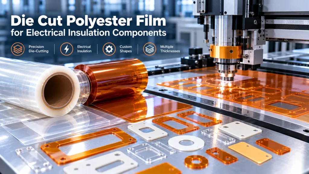
For electrical equipment manufacturers, a die-cut insulation part is more than a piece of plastic shaped to a drawing. It must fit the assembly, protect the intended electrical interface and remain reliable through installation and service. Polyester (PET) film is a widely considered substrate for such parts, but success depends on the specific film grade, the part geometry, the converting method and the validation plan.
This guide focuses on engineering decisions and RFQ preparation for custom die-cut polyester film components—not on unverified temperature ratings, generic claims of certification or assumed production tolerances.
1. Why Die-Cut Polyester Film Is Used in Electrical Insulation
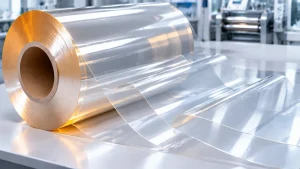
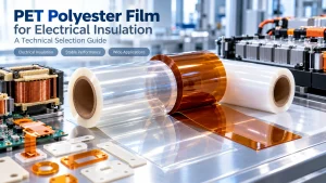
Polyester film, commonly called PET film, is a flexible polymer substrate that can be converted into washers, barriers, spacers, liners, tabs, shields and other custom-shaped electrical insulation components. Biaxially oriented PET (BOPET) is often considered because it combines dielectric behavior, tensile integrity and convertibility. However, an insulation part is not defined by its polymer name alone: film grade, thickness, edge quality, operating environment and assembly geometry determine suitability. Die cutting turns a continuous film into a repeatable component that fits a defined interface. It does not by itself establish an electrical rating or safety certification.
Electrical separation versus mechanical protection
In an assembly, a PET barrier may separate conductive surfaces, protect against abrasion, isolate a fastener or cover an exposed edge. Designers must account for through-thickness dielectric stress as well as surface leakage paths, sharp metal edges, trapped particles, pressure points and assembly movement. Creepage and clearance requirements belong to the complete equipment design and cannot be inferred from film thickness alone.
2. Material Properties That Matter Before Die Cutting
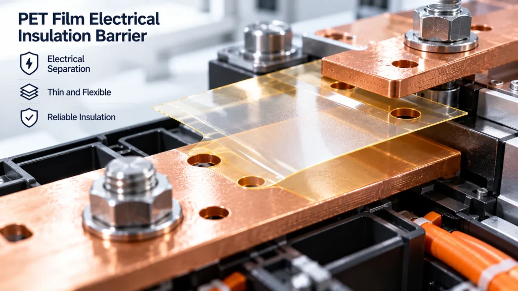
Electrical properties
Request grade-specific dielectric breakdown data, volume and surface resistivity where relevant, and conditioning details. ASTM D149 or IEC 60243-1 may be used for dielectric strength; ASTM D257 or applicable IEC 62631 methods may support resistivity evaluation. These are test methods, not evidence that a particular HTM grade has passed them. Laboratory breakdown results must not be used as an automatic design voltage.
Thermal and environmental limits
Specify continuous service temperature, peak excursions, exposure duration, humidity, cleaning chemicals and any thermal cycling. PET may shrink, age, hydrolyze or change mechanical behavior under unsuitable conditions. Heat-resistant marketing descriptions do not substitute for a validated thermal endurance profile. Ask for actual grade documentation and test conditions.
Mechanical and dimensional behavior
Consider nominal thickness and tolerance, tensile properties, tear behavior, flexibility, bending radius, puncture risk and film orientation. Die-cut edges, holes and narrow webs introduce local stress concentrations. ASTM D882 can be considered for tensile characterization of thin plastic sheeting; part-level evaluation remains necessary.
3. Choosing the Right PET Construction
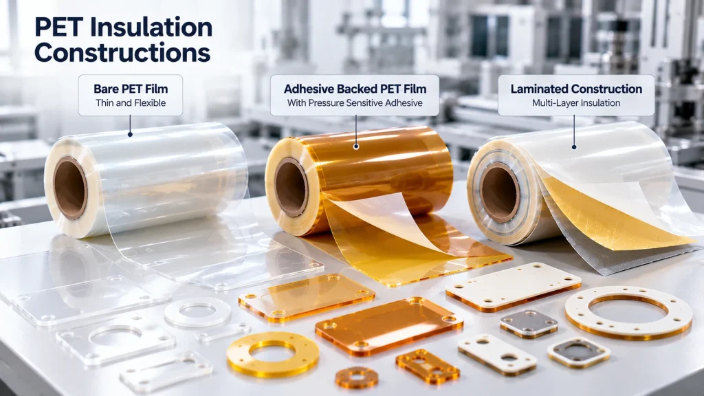
The best construction depends on whether the part is retained mechanically, bonded to a substrate or assembled as part of a multilayer insulation system.
| Construction | Typical design advantage | Important limitation | RFQ detail |
|---|---|---|---|
| Uncoated PET film | Thin barrier without adhesive layer | Requires retention or capture in assembly | Grade, thickness, finish, shape |
| Single-sided adhesive PET | Locates barrier on a defined surface | Adhesive aging, peel and edge lift | Substrate, bond area, adhesive specification |
| Double-sided adhesive PET | Combines insulation with attachment | Total stack height and bond durability | Both substrates, liner, installation method |
| PET laminate or composite | Combines functions in one part | Layer compatibility and delamination risk | Full layer stack and validation plan |
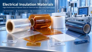
| Alternative PI / PEN / PPS / PTFE | Potential fit for different thermal or chemical conditions | Different cost and converting behavior | Operating profile and reason for substitution |
Film color, transparency and matte finish are not substitutes for a grade-specific electrical specification. A trade name such as Mylar should not be assumed to identify every polyester film.
4. Design for Manufacturability: Geometry, Tolerances and Drawings
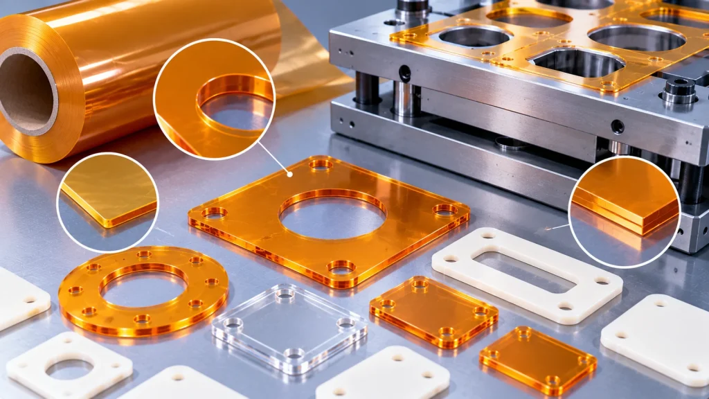
Define functional datums
Identify the features that control assembly fit: mounting holes, slots, outer perimeter, conductor exclusion zones and locating tabs. Use a controlled drawing with units, revision, material callout, critical-to-quality dimensions and datum references. Avoid specifying unnecessarily tight tolerances on every dimension.
Account for cut-edge behavior
Small internal radii, thin bridges, closely spaced holes and narrow adhesive webs may increase tearing, distortion or stripping difficulty. Tool choice—steel-rule die, rotary die or digital cutting—depends on material, geometry, volume and economics. Do not assume a universal minimum hole size, corner radius or tolerance. HTM’s public die-cutting page states that final tolerances are subject to drawing review.
Adhesive and liner design
Specify kiss-cut versus through-cut, liner split or tab, matrix removal, peel direction and whether the part is supplied individually, on sheets or on rolls. For automated application, include pitch, orientation, unwind direction and registration requirements. If adhesive is used, clarify whether the drawing dimensions apply to the PET substrate, adhesive footprint or complete laminate.
5. Industrial Applications and Assembly Interfaces
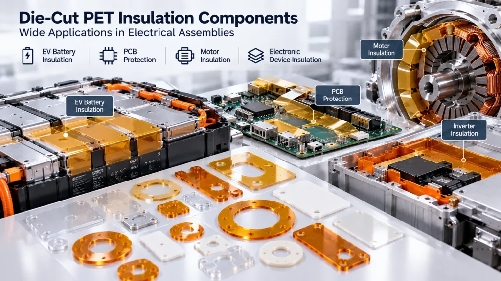
Battery packs and energy storage
Custom barriers can isolate conductive tabs, busbar interfaces, brackets and selected module surfaces. The complete system must be assessed for thermal exposure, electrolyte contact risk, vibration, abrasion, compression and electrical fault conditions. PET is not automatically suitable for every battery location.
PCB, SMT and power electronics
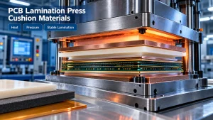
Die-cut parts can isolate a board from a housing, shield local conductors or protect interfaces during assembly. Check component height, soldered edges, contamination, service temperature and whether exposure to soldering or reflow is expected. A PET barrier designed for ambient operation should not be presumed suitable for a reflow profile.
Motors, transformers and industrial equipment
Film shapes may be used as spacers, separators or local insulation components. Review winding geometry, pressure, vibration, varnish compatibility and the applicable insulation system requirements. A film-level property does not establish system-level thermal class.
6. Converting Process: From Roll Stock to Finished Parts
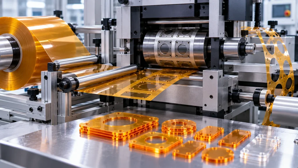
A practical workflow begins with approved incoming film and an agreed drawing revision. Material is conditioned as appropriate, slit or laminated when required, die cut, stripped of waste, inspected and packaged for assembly. For adhesive-backed parts, liner integrity and adhesive exposure during handling deserve special attention.
Choosing delivery format
Loose pieces may suit low-volume manual assembly. Sheeted parts can aid kitting and inspection. Kiss-cut parts on a liner may support automated pick-and-place or high-throughput application. Compare unit price together with tooling, scrap, operator time, handling damage and installation yield—not unit material cost alone.
For a broader comparison, see Roll vs Sheet vs Die-Cut Parts. HTM also publishes information on custom die-cutting services and film laminating. All part-specific capabilities remain subject to engineering review.
7. Common Failure Modes and Prevention
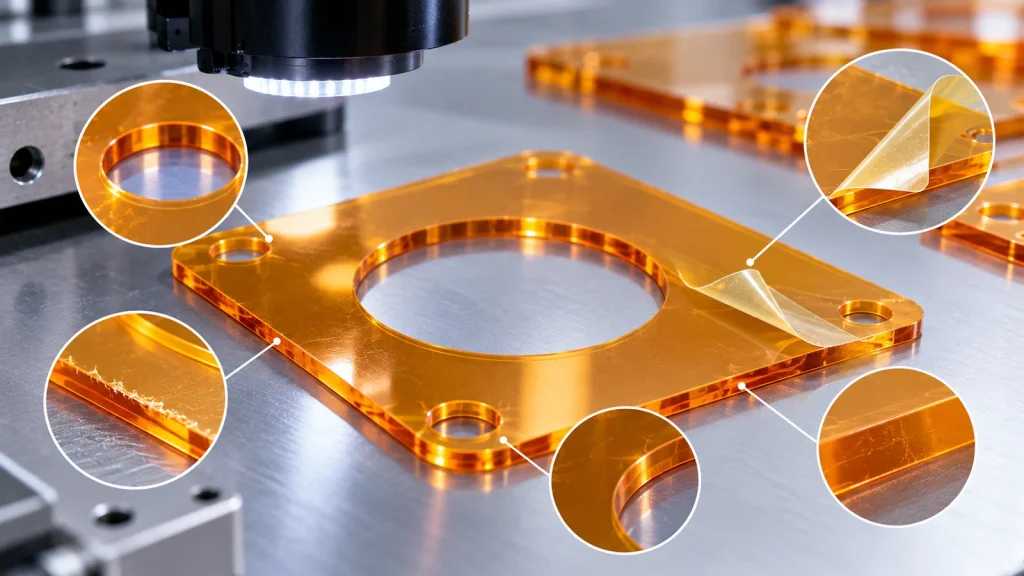
| Observed problem | Possible cause | Prevention or verification |
|---|---|---|
| Electrical breakdown or tracking | Insufficient design margin, contamination, edge damage or humidity | System-level electrical review; controlled cleanliness and appropriate tests |
| Torn bridges or cracked corners | Sharp geometry, tensile stress, unsuitable cutting setup | Radius review, tool trial and edge inspection |
| Hole misalignment | Datum mismatch, film movement, thermal change | Drawing control, registration checks and assembly trials |
| Adhesive edge lifting | Surface energy, contamination, temperature or inadequate pressure | Substrate-specific peel/aging validation and installation controls |
| Warping or shrinkage | Unqualified thermal exposure or lamination stress | Conditioned dimensional checks and thermal cycling |
| Delamination | Layer incompatibility or unsuitable process | Construction qualification and adhesion testing |
Frequent specification errors include selecting by nominal thickness alone, assuming the adhesive shares the film’s temperature capability, using unrealistic tolerances, omitting the release liner, and failing to identify which dimensions are safety-critical.
8. Testing and Qualification for Die-Cut Insulation Parts
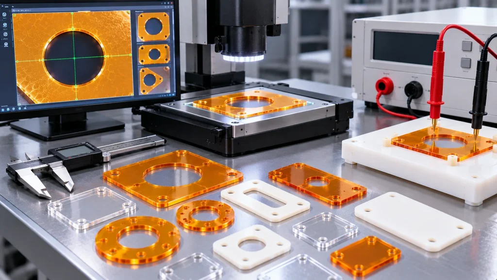
Qualification should connect raw-material properties to the finished geometry and the assembled device. Agree on acceptance criteria before testing. Relevant activities may include:
- Material identity, supplier grade and certificate/document review, where available.
- Thickness and dimensional measurement using an agreed sampling plan and measurement method.
- Visual inspection for burrs, nicks, particles, wrinkles, adhesive contamination and liner damage.
- Dielectric testing using a method suited to film or the actual component; distinguish coupon data from part-level results.
- Thermal aging and thermal cycling under the intended service profile, with post-exposure dimensional and electrical checks.
- Peel, shear or tack testing where adhesive is present, on the actual mating substrate.
- Assembly fit, handling, installation repeatability and vibration or abrasion evaluation where relevant.
ASTM D149, ASTM D257, ASTM D882 and IEC 60243-1 are examples of potentially relevant methods, not a universal mandatory test plan. Any flame classification, UL recognition or compliance statement requires documentation tied to the exact material grade, thickness and conditions. Do not infer certification from a website product title.
9. Engineering Selection and Drawing Review Workflow
- Define the electrical function: barrier location, voltage conditions, fault assumptions and required clearances.
- Capture the environment: operating temperature, thermal peaks, moisture, chemicals, compression and service life.
- Screen materials: PET versus other films using verified grade-level data and cost targets.
- Define the construction: bare film, adhesive-backed or multilayer, including total stack thickness.
- Release the drawing: datums, tolerances, critical features, cut type, orientation and revision.
- Choose presentation: loose pieces, sheets or kiss-cut roll with liner specifications.
- Prototype and validate: inspect fit, electrical function, thermal exposure and adhesive behavior as applicable.
- Approve production controls: sample plan, traceability, packaging and change notification expectations.
Material substitutions and tolerance changes should be approved through the customer’s engineering change process rather than silently applied during quoting.
10. RFQ Checklist for Custom Die-Cut PET Insulation Parts
To receive a technically meaningful quotation, include:
- Application, assembly location and the insulation function.
- Preferred polymer and exact grade, or permission to propose alternatives.
- Nominal thickness, thickness tolerance, color and surface finish.
- Continuous and peak temperatures, exposure time, humidity and chemicals.
- Electrical design requirements and applicable test or compliance standards.
- 2D drawing (PDF) and preferably DXF/DWG, with revision, units, datums and tolerances.
- Part dimensions, holes, internal corners and critical-to-quality features.
- Adhesive type, bonding substrate, release liner, kiss-cut or through-cut requirements.
- Delivery format, roll pitch/orientation, packaging and cleanliness requirements.
- Prototype quantity, annual demand, batch sizes, delivery location and target schedule.
- Required inspection report, material documentation and sample approval process.
When exact grades, compliance documents or tolerances are unknown, mark them “to be confirmed” rather than supplying unsupported assumptions.
11. Frequently Asked Questions
1. Is die-cut PET film suitable for electrical insulation?
It can be suitable when the selected grade, thickness, geometry and assembly environment meet the design requirements. Film-level dielectric properties alone do not establish safety of the finished device.
2. What is the difference between PET and polyester film?
In many industrial film contexts, polyester film refers to polyethylene terephthalate (PET), frequently biaxially oriented PET. Confirm the exact resin and grade in the specification.
3. Can polyester insulation film be supplied with adhesive backing?
Adhesive-backed constructions are possible. Adhesive chemistry, coating thickness, liner and substrate compatibility must be reviewed for the intended use.
4. What die-cutting tolerance can I specify?
There is no universal tolerance for every PET part. Achievable accuracy depends on thickness, geometry, tooling, size, registration and measurement method. Agree on critical tolerances after drawing review and sample trials.
5. Is kiss cutting better than through cutting?
Kiss cutting is useful when parts must remain on a carrier liner; through cutting separates the full construction. The best method depends on installation, liner design and delivery format.
6. Can PET die-cut parts be used in EV batteries?
Potentially, for selected locations. Battery designs require application-specific assessment of electrical, thermal, chemical, mechanical and fault conditions.
7. How do I choose between PET and polyimide?
Compare actual grade data for temperature exposure, electrical needs, mechanical behavior, converting requirements and total cost. Polyimide may be considered for higher-temperature duties, but the correct choice is application-specific.
8. What files should accompany an RFQ?
Send a dimensioned drawing with revision, material and thickness, plus a DXF/DWG where possible, assembly details, test requirements and forecast quantities.
9. Do die-cut parts automatically retain the base film’s certification?
No. Any compliance claim must be checked for the exact grade, thickness, construction, conversion and intended use. Finished assemblies may need separate evaluation.
10. Should I buy parts loose or on a release liner?
Loose parts may be practical for manual assembly. Liner-carried parts can improve automated handling, but require defined pitch, orientation, peel behavior and packaging.
12. Request a Custom Die-Cut Polyester Film Quote
HighTemp Material works with industrial buyers on PET insulation films and project-specific converting requirements. If you need custom die-cut polyester film components, send your drawing and application details for a material and manufacturability review. We can discuss film construction, adhesive options, inspection expectations, sample needs and quotation assumptions; final feasibility and specifications are subject to confirmation.
Request an RFQ: include the material type, application, temperature profile, electrical requirements, thickness, drawing, test standards and estimated purchasing volume.
Review HTM’s custom die-cutting service or explore the PET electrical insulation film product page.