
Electrical insulation materials are essential to the safety, reliability, and long-term performance of electronic and electrical systems. From compact electronic assemblies and printed circuit boards to electric vehicle battery packs, motors, transformers, and industrial power equipment, insulation materials help prevent unintended current flow and maintain electrical separation between conductive components.
However, selecting an electrical insulation material involves much more than choosing a film with a high dielectric strength value.
Engineers must also evaluate operating temperature, insulation thickness, mechanical stress, moisture exposure, chemical compatibility, manufacturing processes, aging behavior, and applicable safety requirements.
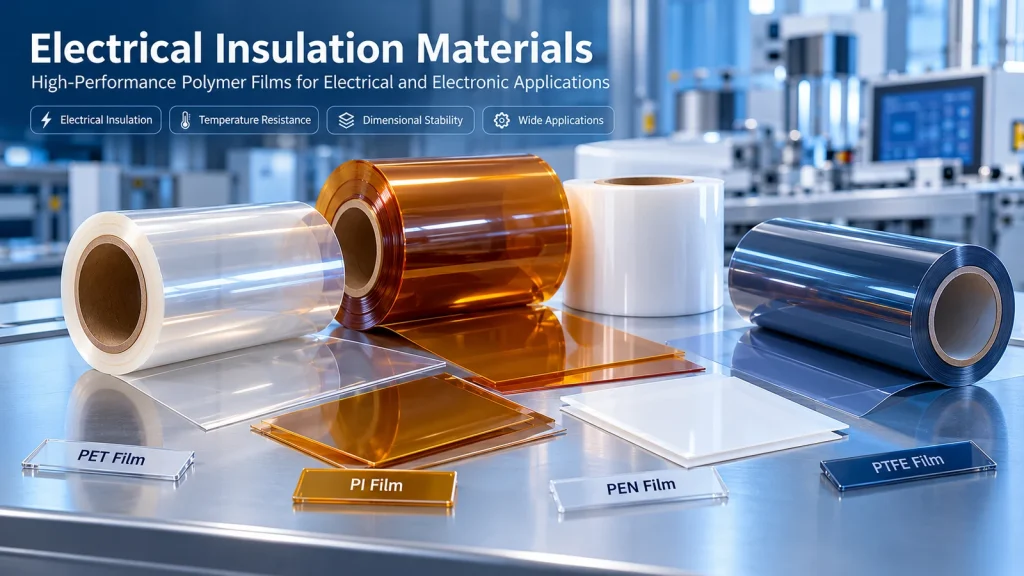
For applications involving thin-film electrical insulation, materials such as polyethylene terephthalate (PET), polyimide (PI), polyethylene naphthalate (PEN), and polytetrafluoroethylene (PTFE) offer different combinations of electrical, thermal, mechanical, and processing properties.
This guide explains the major types of electrical insulating materials, their key performance characteristics, common industrial applications, failure mechanisms, and practical selection methods.
1. What Are Electrical Insulation Materials?
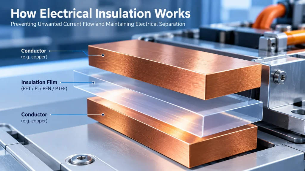
Electrical insulation materials are materials used to restrict unwanted electrical current flow, separate conductive components, and support the electrical integrity of a system.
In practical engineering applications, they may serve as:
- Dielectric barriers between conductors.
- Insulation layers in electronic assemblies.
- Flexible insulating films around electrical components.
- Slot liners and phase insulation in electrical machines.
- Electrical isolation layers in battery and power electronics assemblies.
- Die-cut insulation pads, spacers, and protective barriers.
- Insulating substrates or backing materials in adhesive constructions.
Electrical insulating materials are not necessarily perfect nonconductors. Their electrical behavior depends on applied voltage, temperature, moisture, contamination, geometry, frequency, and exposure duration.
An insulation material that performs adequately under one operating condition may fail under another.
For example, a thin polymer film may demonstrate high dielectric breakdown strength in a standardized laboratory test but still be unsuitable for an assembly exposed to sharp metal edges, repeated flexing, thermal cycling, or sustained electrical stress.
Therefore, successful insulation design requires evaluating both the material and the complete application environment.
Electrical Insulation vs. Thermal Insulation
Electrical insulation and thermal insulation are different engineering functions.
Electrical insulation restricts electrical current flow and maintains dielectric separation.
Thermal insulation reduces heat transfer.
Some materials provide both functions, but good electrical insulation does not automatically mean low thermal conductivity.
For example, electrically insulating thermal interface materials may be engineered to conduct heat while preventing electrical contact.
When selecting materials for batteries, power electronics, or industrial equipment, engineers should define electrical isolation and heat-transfer requirements separately.
2. Major Types of Electrical Insulating Materials
Electrical insulation materials can be classified into polymer films, rigid polymer components, composite laminates, inorganic materials, and insulating coatings.
Each category offers different advantages depending on the application’s electrical, thermal, mechanical, and manufacturing requirements.
2.1 PET Polyester Film
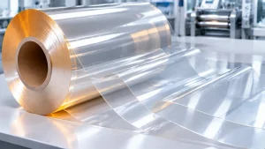
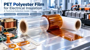
Polyethylene terephthalate (PET) film is widely used in industrial electrical insulation because of its combination of dielectric properties, mechanical strength, dimensional consistency, and processing versatility.
Typical applications include:
- Electrical insulation barriers.
- Die-cut insulating components.
- Flexible insulation layers.
- Industrial electronic assemblies.
- Laminated insulation constructions.
- Selected motor and transformer insulation systems.
PET films are available in different formulations, thicknesses, surface finishes, and treatment conditions.
However, not all PET films are interchangeable.
Standard PET grades, heat-stabilized PET films, and flame-retardant PET formulations may differ significantly in their performance and qualification requirements.
Engineering consideration: PET should be selected based on the actual thermal environment, electrical stress, mechanical design, and verified grade-specific data. General polymer properties should not be treated as guaranteed product specifications.
2.2 Polyimide (PI) Film
Polyimide films are commonly considered for applications involving elevated temperatures, demanding electrical insulation requirements, and compact electronic assemblies.
Potential applications include:
- Flexible printed circuits.
- Electronic insulation components.
- High-temperature electrical barriers.
- Semiconductor and electronics manufacturing processes.
- Electrical insulation tapes.
- Precision die-cut insulation parts.
PI film may offer advantages where conventional polyester films do not meet the required thermal conditions.
However, performance depends on the specific polyimide formulation, film construction, thickness, and exposure environment.
Polyimide should not be selected solely on the assumption that every PI grade has identical temperature or electrical performance.
2.3 PEN Film
Polyethylene naphthalate (PEN) film is a polyester-family material considered in applications requiring a different balance of thermal, dimensional, mechanical, and electrical properties from conventional PET.
Potential applications include:
- Electrical insulation films.
- Flexible electronic components.
- Industrial laminated structures.
- High-performance electrical assemblies.
Certain PEN grades may provide improved thermal or dimensional performance compared with selected PET grades.
Nevertheless, the comparison must be made using representative technical data under equivalent test conditions.
2.4 PTFE Film
Polytetrafluoroethylene (PTFE) film is valued for its chemical resistance, electrical insulation characteristics, low surface energy, and low-friction behavior.
PTFE may be suitable for:
- Electrical isolation in chemically demanding environments.
- Industrial insulation components.
- Specialized electronic assemblies.
- High-temperature processing applications.
- Non-stick or release-related applications where electrical properties are also relevant.
PTFE has important design limitations.
Its low surface energy can complicate adhesive bonding, and its mechanical response under sustained load must be considered when dimensional stability or compression resistance is critical.
Surface-treated or specially constructed PTFE materials may be needed for adhesive-backed insulation components.
2.5 Other Electrical Insulation Materials
Other insulation material categories include:
Mica: Used in selected high-temperature and electrical insulation applications, often as part of engineered composite constructions.
Ceramics: Used where electrical insulation, high-temperature performance, or structural rigidity is required.
Epoxy and fiberglass laminates: Used for rigid electrical insulation components and structural support.
Silicone-based materials: Used in selected flexible insulation, sealing, cushioning, and thermal-management constructions.
Paper and aramid-based insulation: Used in certain electrical machines, transformers, and insulation systems.
The appropriate choice depends on the operating conditions and the required material form.
3. PET vs. PI vs. PEN vs. PTFE: Electrical Insulation Film Comparison
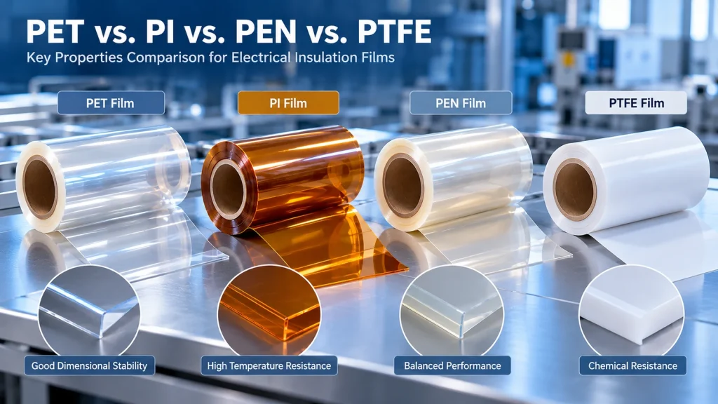
Selecting the right polymer film requires balancing electrical performance, thermal resistance, mechanical behavior, processing compatibility, and total application cost.
PET film is frequently considered for electrical insulation components requiring dimensional consistency and economical converting. Polyimide film may be preferable when higher processing or operating temperatures are involved. PEN and PTFE offer additional options for applications with more specialized requirements.
For a detailed comparison of thermal resistance, electrical insulation, and cost, see our PI vs PET Film: Temperature Resistance, Insulation and Cost Comparison.
Engineers considering fluoropolymer insulation can also review our PTFE Film: Properties, Temperature Resistance and Industrial Applications guide for additional information on PTFE material behavior and industrial applications.
For flexible film-based insulation applications, the following comparison provides a useful starting point.
| Selection Factor | PET Film | PI Film | PEN Film | PTFE Film |
|---|---|---|---|---|
| Electrical insulation | Grade-dependent; widely used | Grade-dependent; widely used | Grade-dependent | Grade-dependent; often suitable for demanding dielectric applications |
| Elevated-temperature applications | Requires careful grade selection | Often a strong candidate | Certain grades offer advantages over conventional PET | Often a strong candidate |
| Mechanical handling | Generally suitable for film converting | Depends on grade and thickness | Depends on grade and thickness | Requires attention to deformation and handling |
| Adhesive bonding | Surface and adhesive compatibility must be checked | Surface and adhesive compatibility must be checked | Surface and adhesive compatibility must be checked | Low surface energy can make bonding difficult |
| Chemical exposure | Verify against chemicals and conditions | Verify against chemicals and conditions | Verify against chemicals and conditions | Broad chemical resistance, subject to application conditions |
| Die-cut processing | Commonly considered | Commonly considered | Feasible with process validation | Feasible with process validation |
| Main selection concern | Thermal aging and environmental exposure | Grade-specific thermal and mechanical behavior | Grade availability and qualification | Creep, bonding, and dimensional behavior |
This comparison is qualitative. It is not a substitute for grade-specific technical data sheets, standardized testing, or application qualification.
How Should Engineers Compare Materials?
A useful comparison should be based on:
- Identical or comparable test methods.
- Similar thicknesses or an appropriate thickness correction.
- Equivalent environmental conditioning.
- Relevant electrical waveforms and operating voltages.
- Comparable thermal exposure durations.
- Actual assembly geometry and manufacturing conditions.
A material comparison based on unrelated supplier data sheets may produce misleading conclusions if the testing conditions differ.
4. Key Electrical Properties of Insulation Materials
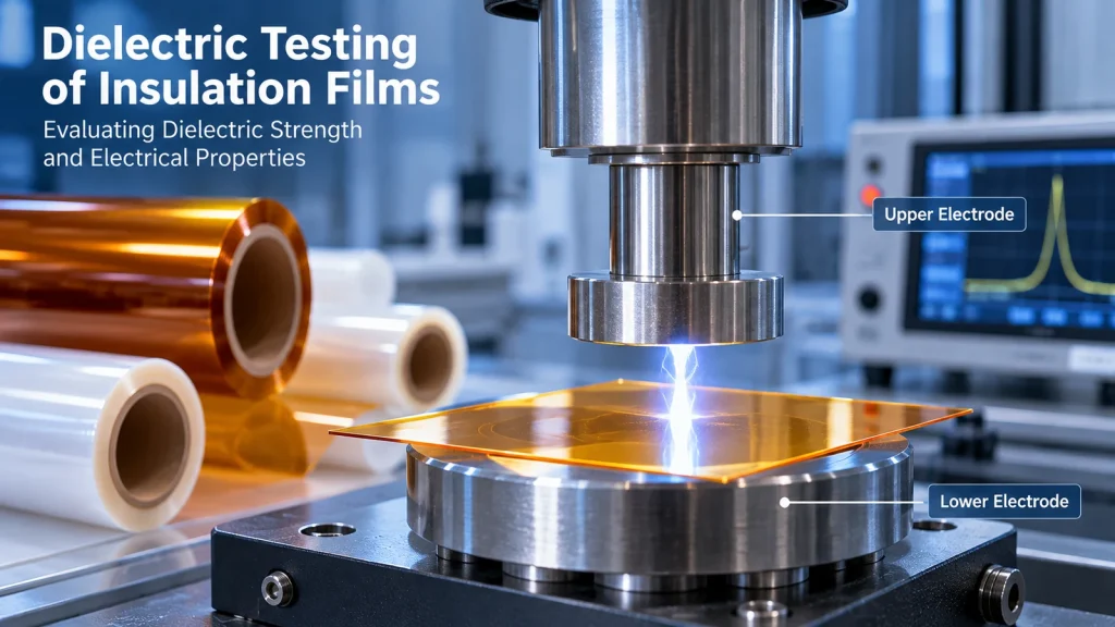
Dielectric strength, dielectric constant, volume resistivity, and surface resistivity describe different aspects of electrical insulation performance.
These parameters should not be used interchangeably. Dielectric strength concerns breakdown under specified testing conditions, while dielectric constant describes a material’s response to an electric field. Resistivity measurements address electrical conduction through the material or along its surface.
Engineers should compare test methods, specimen thickness, conditioning, frequency, and temperature before using published data to qualify a material.
4.1 Dielectric Strength
Dielectric strength describes the electrical field level at which a material experiences dielectric breakdown under specified test conditions.
It is commonly expressed in kV/mm or equivalent units.
A simplified average-field relationship is:
Electric field = Applied voltage / Insulation thickness
However, this relationship does not establish a safe operating voltage by itself.
Actual insulation design must account for electrode geometry, defects, field concentration, aging, temperature, contamination, and applicable design margins.
Increasing thickness does not necessarily produce a proportional increase in breakdown voltage.
Relevant test methods include ASTM D149 and IEC 60243-1, depending on material type and application.
4.2 Dielectric Constant
Dielectric constant, also called relative permittivity, describes how a material responds to an applied electric field relative to vacuum.
It is relevant to capacitance, signal behavior, and electric-field distribution.
In electronic applications, engineers should evaluate dielectric constant at the relevant frequency and temperature.
A dielectric constant measured at one frequency may not accurately represent behavior under different operating conditions.
4.3 Volume Resistivity
Volume resistivity describes resistance to electrical current flow through the bulk of a material under specified conditions.
It is commonly expressed in Ω·cm or Ω·m.
Volume resistivity is useful for comparing insulating materials but is influenced by temperature, moisture, conditioning, and measurement conditions.
ASTM D257 and IEC 62631-series methods may be relevant, depending on the property and material being evaluated.
4.4 Surface Resistivity
Surface resistivity relates to electrical conduction along a material’s surface.
Surface contamination, humidity, processing residues, and environmental exposure can significantly affect surface insulation performance.
For assemblies exposed to dust, condensation, or chemical residues, surface behavior may be as important as bulk electrical properties.
4.5 Dielectric Loss
Dielectric loss describes energy dissipation in a dielectric material subjected to an alternating electric field.
This parameter becomes particularly important in high-frequency or high-voltage applications where electrical losses and heating may affect performance.
4.6 Tracking and Partial Discharge
Electrical tracking refers to the development of conductive paths along an insulating surface under certain electrical and environmental conditions.
Partial discharge refers to localized electrical discharges that do not completely bridge the insulation between conductors.
Both can contribute to long-term insulation deterioration in relevant electrical systems.
Tracking resistance and partial-discharge behavior require application-specific evaluation; neither can be inferred from dielectric strength alone.
5. Thermal Properties and Temperature Resistance
Temperature resistance is a critical consideration when selecting polymer films for electrical insulation.
Continuous operating temperature, short-term peak temperature, and processing temperature must be evaluated separately. A film that survives a brief thermal exposure is not necessarily suitable for sustained operation at that temperature.
Repeated thermal cycling can also contribute to dimensional changes, mechanical fatigue, and deterioration of bonded insulation constructions.
For a practical comparison of PET and PI temperature behavior, refer to our PI vs PET Film Selection Guide.
Continuous Operating Temperature vs. Short-Term Exposure
A material’s ability to tolerate a brief thermal event does not establish its suitability for long-term service at the same temperature.
Engineers should distinguish between:
Continuous service conditions: Sustained exposure during normal operation.
Peak exposure: Short-duration temperature excursions.
Processing temperature: Temperature encountered during lamination, soldering, curing, or assembly.
Thermal aging: Property changes resulting from cumulative exposure over time.
A material that survives a short production process may still be unsuitable for years of operation at elevated temperature.
Thermal Classifications and Insulation Systems
In electrical equipment, thermal classification may apply to an insulation material or an insulation system under defined standards and qualification conditions.
A material’s individual thermal properties do not automatically qualify a complete motor, transformer, or electrical insulation system for a particular thermal class.
Where required, engineers should consult the applicable IEC or UL standards and system-level qualification evidence.
6. Mechanical and Environmental Selection Factors
Electrical properties alone are insufficient for many industrial insulation designs.
Film Thickness
Thickness influences mechanical handling, dielectric performance, assembly clearance, flexibility, and cost.
An unnecessarily thick film may increase stiffness or interfere with compact assembly requirements.
An excessively thin film may be more vulnerable to puncture, handling damage, or manufacturing variation.
The correct thickness should be selected using electrical design requirements, mechanical testing, and validated tolerances.
Tensile Strength and Elongation
These properties are relevant when insulation films undergo tension, bending, forming, or die-cut processing.
Mechanical performance can vary with film orientation, temperature, thickness, and aging.
Dimensional Stability
Dimensional changes can affect alignment, registration, and fit during precision converting or thermal processing.
This is particularly important for die-cut components with narrow clearances, complex geometries, or multiple registration features.
Moisture and Hydrolysis Resistance
Moisture exposure may affect electrical properties and accelerate degradation in susceptible materials.
PET-based materials, in particular, should be evaluated carefully where high humidity and elevated temperatures occur together.
Chemical Compatibility
Cleaning agents, oils, electrolytes, solvents, flux residues, and processing chemicals may interact with insulation materials.
Compatibility should be evaluated using the actual chemical concentration, temperature, exposure duration, and mechanical stress.
7. Electrical Insulation Materials for Industrial Applications
7.1 Electronics and PCB Manufacturing
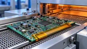
Electronic manufacturing uses insulating films, masking materials, and protective components for electrical separation and process protection.
Selection factors may include:
- Thermal exposure during assembly.
- Film thickness and dimensional control.
- Adhesive residue and contamination.
- Compatibility with cleaning processes.
- Precision die-cut geometry.
- Electrical insulation requirements.
PI films and other engineered materials may be considered where the manufacturing process involves elevated temperatures.
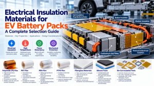
7.2 Electric Vehicle Battery Packs
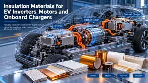
Electrical insulation materials are used in selected battery assemblies to separate conductive components and support electrical isolation.
Potential applications include cell insulation, busbar protection, module isolation barriers, and custom die-cut insulating components.
Material selection depends on operating voltage, temperature, vibration, compression, chemical exposure, and the applicable system safety requirements.
For a more detailed application-specific discussion, read our Electrical Insulation Materials for EV Battery Packs: A Complete Selection Guide.
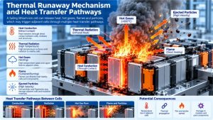
Electrical insulation and thermal runaway propagation protection should be treated as separate design requirements. A material suitable for routine electrical isolation should not automatically be assumed to provide an effective thermal propagation barrier.l propagation barrier require additional, application-specific evaluation.
7.3 Motors and Transformers
Electrical machines use insulation systems to separate conductive components and maintain electrical integrity during operation.
Potential film applications include slot liners, phase insulation, interlayer insulation, and selected composite structures.
Engineers must evaluate thermal aging, electrical stress, mechanical vibration, winding processes, and compatibility with impregnation materials.
7.4 Power Electronics
Inverters, converters, and onboard charging systems may require thin electrical insulation barriers within compact assemblies.
Important considerations include:
- Electrical clearance and insulation coordination.
- Temperature and thermal cycling.
- Dielectric behavior.
- Mechanical fixation.
- Assembly tolerances.
- Long-term aging.
Applicable system standards and qualification requirements should guide the final design.
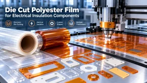
7.5 Custom Die-Cut Insulation Components
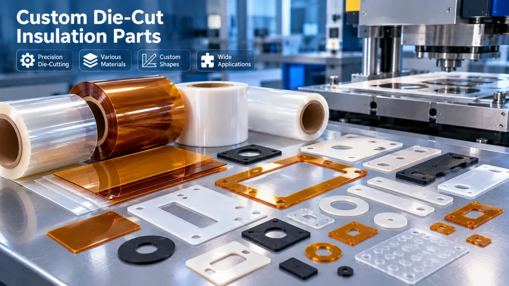
Die-cut insulation films can be designed to fit specific electrical and mechanical geometries.
Applications may involve custom pads, barriers, spacers, washers, and insulating shapes.
Critical design considerations include hole diameter, corner radius, edge quality, dimensional tolerances, adhesive placement, and assembly orientation.
Material selection and converting process capability must be evaluated together.
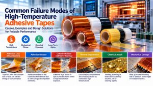
8. Common Electrical Insulation Failure Modes
8.1 Dielectric Breakdown
Possible causes: Excessive electrical stress, material defects, insufficient insulation thickness, contamination, or local field concentration.
Prevention: Validate the insulation design using appropriate electrical tests, representative samples, and relevant safety margins.
8.2 Thermal Aging and Embrittlement
Possible causes: Prolonged exposure to elevated temperatures or repeated thermal cycling.
Prevention: Evaluate thermal aging behavior under representative operating conditions and inspect retained mechanical and electrical properties.
8.3 Mechanical Puncture and Edge Damage
Possible causes: Sharp conductors, burrs, assembly pressure, or handling damage.
Prevention: Improve edge geometry, validate die-cut quality, and perform representative mechanical assembly testing.
8.4 Moisture-Related Deterioration
Possible causes: Humidity, condensation, moisture-sensitive material behavior, or inadequate environmental protection.
Prevention: Assess moisture conditioning, insulation resistance, and long-term environmental exposure.
8.5 Adhesive Delamination
Possible causes: Poor surface compatibility, inadequate preparation, thermal stress, or unsuitable adhesive selection.
Prevention: Test adhesive compatibility, peel performance, thermal aging, and actual assembly conditions.
8.6 Electrical Tracking and Surface Contamination
Possible causes: Surface deposits, moisture, electrical stress, and unfavorable environmental conditions.
Prevention: Maintain suitable insulation geometry, control contamination, and evaluate tracking resistance where relevant.
9. Testing Standards and Material Qualification
Testing should reflect both the insulation material and the intended application.
| Property | Example Test Standard | Engineering Purpose |
|---|---|---|
| Dielectric breakdown strength | ASTM D149 / IEC 60243-1 | Assess breakdown behavior under defined conditions |
| Volume and surface resistivity | ASTM D257 / applicable IEC 62631 methods | Evaluate insulating resistance |
| Tensile properties of thin films | ASTM D882 | Assess tensile behavior |
| Thermal transitions | ISO 11357 series / applicable DSC methods | Characterize thermal transitions |
| Flammability | UL 94, where applicable | Evaluate specified flammability classifications |
| Comparative tracking index | IEC 60112 | Evaluate tracking behavior under specified conditions |
| Environmental aging | Application-specific protocols | Assess performance retention |
| Adhesive performance | Applicable peel and aging methods | Evaluate bonded constructions |
The standards listed are examples, not a declaration that HTM products have been tested or certified under them. Test method selection, current editions, specimen preparation, and applicability must be confirmed.
Recommended Qualification Process
Step 1: Review the material technical data sheet.
Check grade identification, test methods, property units, conditioning, and stated limitations.
Step 2: Define critical-to-quality requirements.
Identify the properties that directly affect product safety, performance, and manufacturability.
Step 3: Test representative material samples.
Use the intended thickness, construction, and processing conditions.
Step 4: Evaluate the actual assembly.
Include edges, holes, fasteners, adhesives, thermal interfaces, and mechanical loading.
Step 5: Conduct environmental and aging tests.
Apply appropriate thermal, humidity, electrical, and mechanical exposure conditions.
Step 6: Confirm production consistency.
Agree on inspection criteria, tolerances, traceability, and change-control requirements.
10. How to Select the Right Electrical Insulation Material
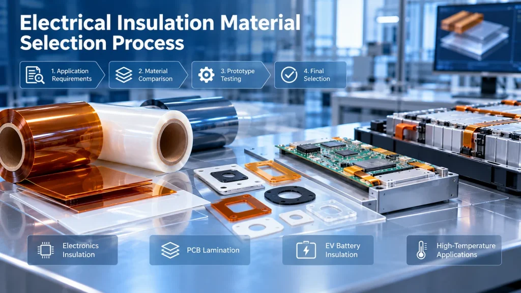
A practical selection process begins with the operating environment rather than the material name.
Step 1: Define Electrical Requirements
Identify operating voltage, transient voltage, waveform, frequency, insulation function, and applicable safety standards.
Determine whether the material will serve as functional, basic, supplementary, reinforced, or another type of insulation under the relevant equipment standard.
Step 2: Define Thermal Conditions
Specify continuous operating temperature, short-term peaks, processing exposure, and required service life.
Step 3: Identify Mechanical Constraints
Consider flexibility, compression, puncture resistance, vibration, film thickness, and installation geometry.
Step 4: Evaluate Environmental Exposure
Assess humidity, cleaning agents, oils, electrolytes, chemicals, and contamination.
Step 5: Select Candidate Materials
Compare PET, PI, PEN, PTFE, and other insulation materials based on the actual requirements.
Step 6: Determine Supply Format
Choose between film rolls, cut sheets, adhesive-backed constructions, or custom die-cut parts based on the production process.
Step 7: Verify Testing and Documentation
Request the technical data, test evidence, and qualification documentation appropriate to the application.
Step 8: Approve Samples Before Production
Confirm performance using representative parts and the actual manufacturing process.
11. How to Evaluate Electrical Insulation Material Suppliers
For OEMs and industrial buyers, supplier selection should address more than material availability.
Important questions include:
- Can the supplier identify the exact material grade and construction?
- Are technical data sheets available for the proposed grade?
- Are the requested thicknesses, widths, and formats available?
- Can the supplier provide samples for engineering evaluation?
- Are thickness tolerances and surface quality requirements defined?
- Is the material suitable for the intended converting process?
- Can relevant testing and documentation requirements be reviewed?
- Are traceability and change-control requirements understood?
- Can the supplier clarify minimum order quantities and lead times?
- Can the supplier support the required inspection and packaging requirements?
For custom insulation components, engineering drawings and process details are often necessary to prepare an accurate quotation.
12. RFQ Checklist for Electrical Insulation Films
When requesting a quotation, provide the following information where available:
| RFQ Item | Information to Provide |
|---|---|
| Material | PET, PI, PEN, PTFE, or alternative |
| Grade | Preferred grade or performance specification |
| Application | Component and end-use environment |
| Electrical requirements | Voltage, insulation function, relevant test requirements |
| Thermal requirements | Continuous and peak temperature exposure |
| Thickness | Nominal thickness and tolerance |
| Format | Roll, sheet, adhesive-backed film, or die-cut part |
| Dimensions | Width, length, part size, or CAD drawing |
| Surface requirements | Treatment, finish, cleanliness, or coating requirements |
| Adhesive requirements | Adhesive type, bonding substrate, and liner requirements |
| Quantity | Sample quantity, trial order, and estimated annual usage |
| Documentation | TDS, test reports, declarations, or other required documents |
| Delivery | Destination, requested timing, and packaging requirements |
Providing this information helps reduce material-selection uncertainty and makes technical quotation discussions more efficient.
13. Frequently Asked Questions
1. What are the most common electrical insulation materials?
Common categories include polymer films such as PET, PI, PEN, and PTFE; rigid polymer laminates; mica; ceramics; insulating papers; and specialized coatings. The appropriate material depends on electrical, thermal, mechanical, and environmental requirements.
2. Which plastic material is best for electrical insulation?
There is no universally best plastic insulation material. PET, PI, PEN, and PTFE offer different advantages. Engineers should compare specific grades and constructions against the intended operating conditions.
3. Is PET film a good electrical insulator?
PET film is widely used in electrical insulation applications. However, suitability depends on the grade, thickness, temperature, electrical stress, environment, and applicable qualification requirements.
4. Is polyimide film better than polyester film?
Polyimide may be advantageous for certain elevated-temperature applications, while polyester films may offer a useful combination of processing performance and cost. The decision should be based on verified grade-specific properties.
5. What is the difference between dielectric strength and dielectric constant?
Dielectric strength concerns electrical breakdown behavior under specified conditions. Dielectric constant describes the material’s response to an electric field relative to vacuum. They measure different properties and should not be used interchangeably.
6. How do I choose the correct electrical insulation film thickness?
Film thickness should be selected based on insulation coordination, electrical testing, mechanical constraints, manufacturing tolerances, and the complete assembly design. A simple thickness calculation is not sufficient to establish safety.
7. Are all electrical insulation films flame retardant?
No. Flammability behavior depends on the material formulation, thickness, and tested construction. Any claimed flammability classification should be supported by appropriate evidence for the specific grade and thickness.
8. Can electrical insulation films be die-cut into custom shapes?
Many insulation films can be converted into custom shapes, subject to material and process suitability. Engineers should specify dimensional tolerances, edge quality, hole geometry, and any adhesive requirements.
9. Which electrical insulation materials are used in EV batteries?
Depending on the battery design, polymer films and other engineered insulation materials may be used for electrical barriers, busbar insulation, and component isolation. Electrical insulation requirements should be distinguished from thermal runaway barrier requirements.
10. What information should I send to an electrical insulation material supplier?
Provide the application, preferred material, thickness, dimensions, electrical and thermal requirements, requested format, quantity, and any relevant drawings or documentation requirements.
14. Request Electrical Insulation Film Samples or a Quotation
Selecting the appropriate electrical insulation material requires balancing dielectric performance, temperature resistance, mechanical reliability, manufacturing compatibility, and cost.
HighTemp Material focuses on industrial high-temperature polymer films and electrical insulation material solutions, including PET, PI, PEN, and PTFE-related applications.
If you are evaluating materials for electronic manufacturing, electrical insulation components, battery assemblies, or custom converting applications, share your requirements with our team.
Tell us about your application:
- Required material or performance specification.
- Film thickness and dimensions.
- Operating temperature and electrical requirements.
- Roll, sheet, or custom die-cut format.
- Estimated quantity and project schedule.
Request a Technical Review or RFQ
Visit HighTemp Material to explore material options and contact our team regarding your project.
Material selection recommendations, product availability, certifications, and performance claims are subject to confirmation for the specific proposed grade and application.