

How to Select PTFE-Coated Fiberglass, Silicone-Coated Fabrics, Release Films and Cushioning Materials for Photovoltaic Module Manufacturing
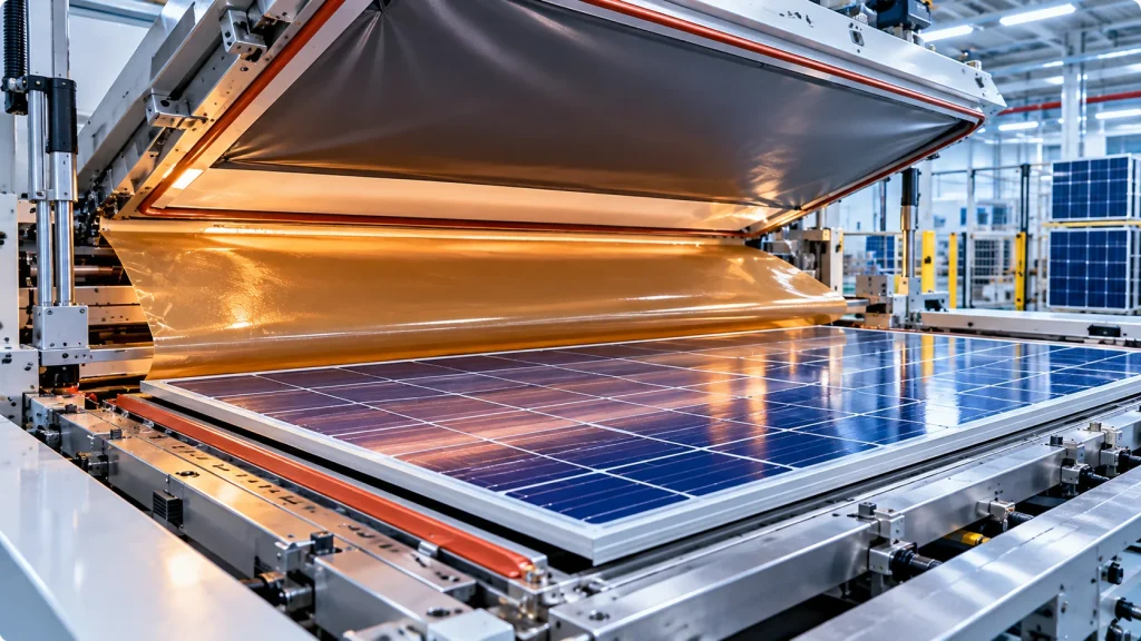
Solar module lamination is a critical manufacturing operation that brings together photovoltaic cells, encapsulation materials, glass and protective back layers into a mechanically integrated module.
The lamination process typically involves controlled heating, vacuum or degassing, and pressure application. The specific sequence depends on the equipment, encapsulant formulation and module construction.
While encapsulation materials such as ethylene-vinyl acetate (EVA) and polyolefin elastomer (POE) become part of the finished module, the laminator also relies on process materials that do not normally remain in the final product.
These include release sheets, coated fabrics, flexible membranes, cushioning layers, protective films and other high-temperature consumables.
Choosing the wrong process material can contribute to sticking, surface marks, wrinkles, contamination, premature wear and inconsistent lamination results.
This guide explains the functions of high-temperature materials used in solar module lamination, compares major material families and provides a practical selection and qualification framework for PV manufacturers, equipment engineers and technical buyers.
1. How Solar Module Lamination Works
A conventional crystalline-silicon PV module contains several functional layers.
Depending on the design, these may include:
- Front glass
- Front encapsulant
- Interconnected solar cells
- Rear encapsulant
- Glass or polymer-based backsheet
During lamination, the encapsulant softens or flows to wet adjacent surfaces and fill spaces within the module assembly. Some encapsulant formulations also undergo crosslinking during the process.
Vacuum or degassing helps remove trapped air and volatile constituents, while controlled pressure brings the layers into intimate contact.
Temperature, Pressure and Time
Three fundamental variables influence the process:
Temperature affects encapsulant softening, flow, wetting and, where applicable, curing.
Pressure affects consolidation and contact between layers.
Time determines how long the materials experience the selected thermal and pressure conditions.
These variables interact. A change in one may require adjustments to the others.
There is no universal lamination recipe suitable for every EVA, POE, EPE or other encapsulation system.
Why Process Consumables Matter
Even if the encapsulant and module construction are correctly specified, damaged or unsuitable laminator consumables may create process defects.
For example, a release sheet with poor surface integrity may transfer marks or residues. A worn flexible membrane may change local pressure application. A cushioning layer with inconsistent thickness or compression behavior may contribute to uneven contact.
Therefore, laminator consumables should be treated as controlled process materials rather than interchangeable accessories.
2. Where High-Temperature Materials Are Used Inside a Solar Laminator
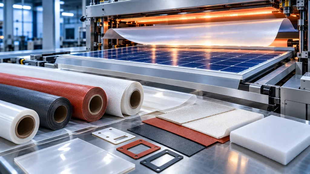
A typical vacuum laminator may include a heated platen, chamber seals, a flexible membrane or bladder, and equipment-specific protective or release layers.
Actual layouts vary among single-chamber, double-chamber, membrane-based and other laminator designs.
Release Surfaces
Release materials help prevent unintended adhesion between the module assembly, excess encapsulant and adjacent processing surfaces.
Flexible Membranes
A silicone rubber membrane or another equipment-specific flexible element may transfer pressure to the module stack.
Its mechanical integrity, elasticity and sealing behavior are essential to its intended function.
Cushioning Layers
Cushioning materials may be used in suitable laminator designs to accommodate local dimensional variations or help manage contact pressure.
Their placement and function must be confirmed with the equipment manufacturer.
Protective Liners and Covers
Selected films or coated fabrics may protect processing surfaces against contamination or abrasion.
A protective liner should not be assumed to provide the same performance as a pressure membrane or a release sheet.
Key engineering principle: Each consumable must be selected according to its installed location and function, not merely its advertised temperature resistance.
3. PTFE-Coated Fiberglass Release Sheets
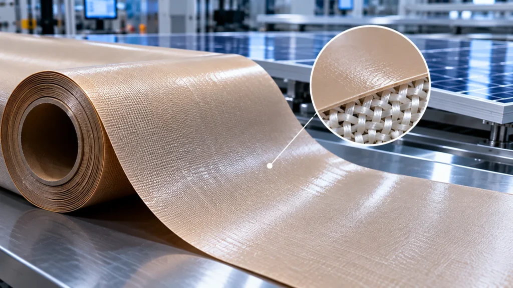
PTFE-coated fiberglass is an important material family for industrial release applications.
It combines a woven fiberglass reinforcement with a PTFE-based surface coating.
The fiberglass substrate contributes dimensional reinforcement, while the coating provides low surface energy and release characteristics.
Why PTFE-Coated Fiberglass Is Considered
Depending on its construction, PTFE-coated fiberglass can provide:
- A low-adhesion processing surface
- Dimensional reinforcement
- Resistance to selected processing chemicals
- A reusable release surface
- Suitability for cutting into equipment-specific shapes
These characteristics make it a candidate for release sheets and protective liners in suitable lamination equipment.
Important Selection Properties
Surface release behavior: The sheet must release cleanly from the actual encapsulant residue or contacting surface.
Coating integrity: Pinholes, scratches, exposed fiberglass and uneven coating may affect cleanliness and service life.
Thickness and flatness: Thickness variation or wrinkles can influence contact conditions.
Dimensional stability: The sheet should maintain acceptable dimensions throughout repeated thermal cycles.
Mechanical durability: Repeated handling, cleaning and flexing can damage the coating or reinforcement.
Smooth Versus Textured Constructions
A smooth coated surface may be preferred where surface marking is a concern.
More pronounced fabric texture may influence the surface appearance of contacting materials.
The acceptable texture depends on whether the sheet contacts the finished module surface, excess encapsulant or another equipment component.
Limitations
PTFE-coated fiberglass is not automatically suitable for every laminator.
It may develop creases, coating wear, edge fraying or localized contamination over time.
The correct construction must be validated against the actual process.
For a broader comparison, see Silicone-Coated Fiberglass vs PTFE-Coated Fiberglass Fabric.
4. Silicone-Coated Fiberglass and Silicone-Based Components
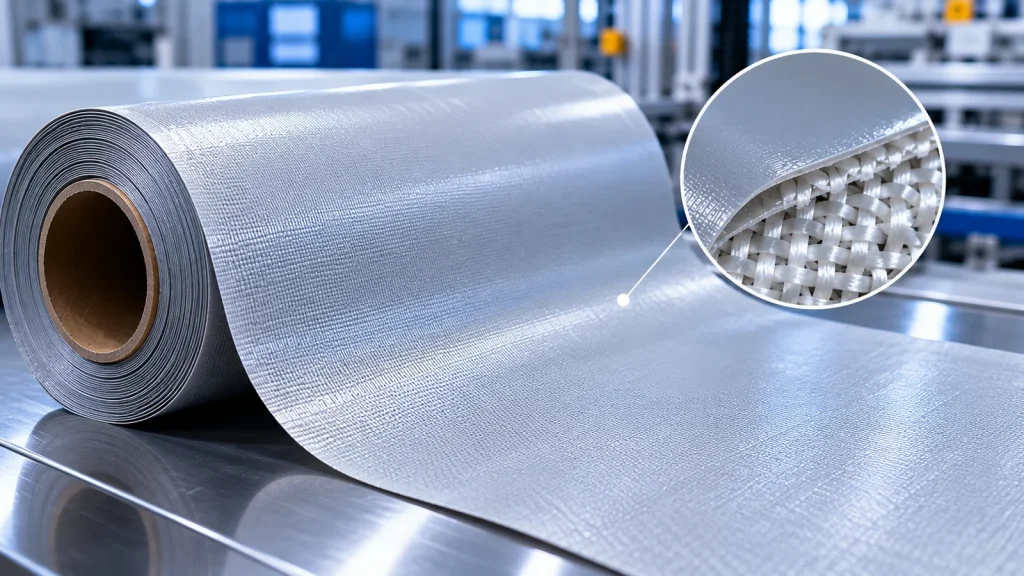
Silicone-coated fiberglass combines a glass-fiber fabric with a silicone elastomer coating.
It generally offers a different balance of flexibility, surface characteristics and mechanical behavior from PTFE-coated fiberglass.
Potential Applications
Depending on the grade and equipment design, silicone-coated fiberglass may be evaluated for:
- Flexible protective covers
- Equipment liners
- Thermal protection components
- Sealing-related applications
- Selected cushioning or contact layers
However, silicone-coated fiberglass fabric should not be confused with a solid silicone rubber laminator membrane.
Silicone Rubber Membranes
A laminator membrane must satisfy requirements related to pressure transfer, elasticity, sealing, flexural fatigue and thermal aging.
These requirements are not established by the properties of silicone-coated fiberglass alone.
A fabric-reinforced construction may have very different deformation behavior from an unreinforced rubber membrane.
Silicone Surface Considerations
Silicone-based materials can offer useful flexibility and compliance.
However, surface release behavior, contamination risk and compatibility with the encapsulant must be tested.
Silicone transfer or residue may be unacceptable for certain manufacturing processes.
When to Consider Silicone-Coated Fiberglass
This material family is worth evaluating when flexibility, mechanical protection or environmental resistance is more important than achieving the lowest possible adhesion.
For a material overview, see Silicone Coated Fiberglass Cloth.
5. Cushioning Materials and Pressure Uniformity
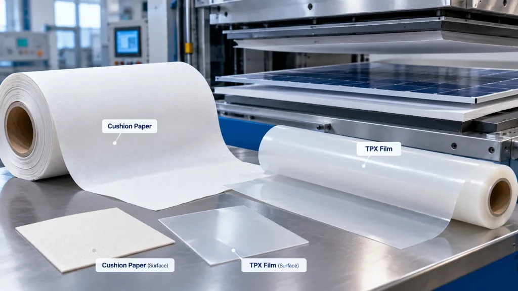
Pressure uniformity is important in lamination because PV modules contain materials with different stiffness, thickness and thermal expansion behavior.
Glass, cells, interconnect ribbons and encapsulants respond differently to heat and mechanical loading.
What Cushioning Materials Do
In appropriate equipment configurations, cushioning layers may help:
- Accommodate limited thickness variations
- Reduce localized contact stress
- Protect surfaces against hard contact
- Improve conformity at selected interfaces
The actual effect depends on the layer position, stiffness, thickness and compression behavior.
Material Families to Evaluate
Possible candidates include engineered silicone rubber sheets, silicone-based composite cushions and other equipment-qualified compressible materials.
A paper-based cushion or other fibrous construction should only be considered if the specific process and equipment permit it.
A material used successfully in PCB lamination is not automatically suitable for solar module lamination.
Key Properties
Compression response: The material must deform appropriately under the relevant pressure and temperature.
Compression set: Permanent deformation can reduce its ability to provide consistent contact over repeated cycles.
Thermal aging: Repeated heating may change hardness, elasticity or dimensions.
Thickness uniformity: Local variations can influence the pressure distribution.
Contamination: Fibers, particles or extractable constituents may create cleanliness concerns.
Avoid Excessive Compliance
More cushioning is not necessarily better.
An overly soft or thick layer may alter pressure transfer, heating response or dimensional control.
Engineers should evaluate the complete equipment stack rather than selecting cushioning solely by softness.
6. Release Films Versus Encapsulation Films
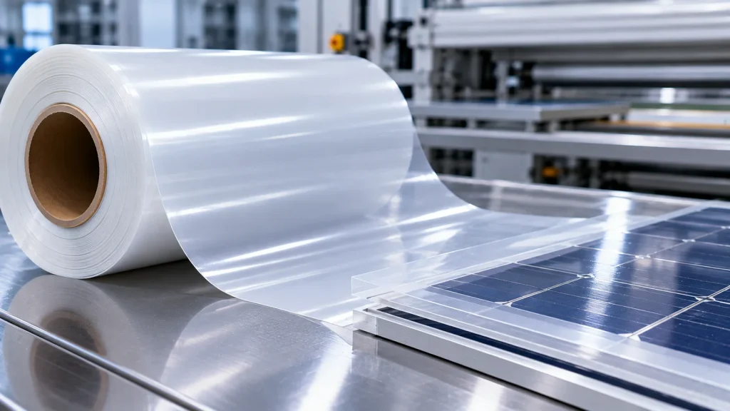
The terms release film and encapsulation film describe different functions.
Encapsulation Films
EVA, POE and other qualified encapsulation films are designed to remain inside the finished solar module.
They contribute to bonding, mechanical protection and environmental durability.
Their selection affects the long-term reliability of the finished module.
Release Films
A release film is a temporary processing material.
It may be used to separate surfaces, prevent sticking or protect equipment, depending on the laminator configuration.
Candidate film families may include suitable fluoropolymer films and other specially engineered release constructions.
Their use must be verified for the actual temperature, pressure, contact conditions and reuse requirements.
Why the Distinction Matters
An encapsulation film is selected for adhesion and long-term service inside the module.
A release film is selected for controlled separation and processing compatibility.
These requirements can be fundamentally different.
Material Selection Table
| Material or Construction | Main Function | Potential Advantages | Important Limitations |
|---|---|---|---|
| PTFE-coated fiberglass | Reusable release or protective surface | Low adhesion, reinforced construction | Coating wear, wrinkles, surface texture |
| Silicone-coated fiberglass | Flexible protective or equipment component | Flexibility, reinforced structure | Grade-specific release and compression behavior |
| Silicone rubber membrane | Pressure transfer and chamber function | Flexible deformation and sealing potential | Aging, fatigue, tears, compression changes |
| Engineered cushioning sheet | Local compliance and contact management | Can accommodate selected thickness variations | Compression set, contamination, dimensional change |
| Qualified fluoropolymer release film | Temporary separation or surface protection | Release behavior and potentially smooth surfaces | Cost, handling, thickness and temperature limits |
| EVA/POE encapsulant | Permanent module encapsulation | Designed for bonding and module integration | Not a reusable laminator release material |
This table describes general material functions. It does not establish suitability for a particular laminator or material grade.
7. Critical Material Properties for Engineering Selection
7.1 Thermal Stability
Evaluate the actual thermal profile, including repeated exposure and local hot spots.
Short-term temperature resistance is not equivalent to long-term service life.
7.2 Release Performance
Test release behavior against the real encapsulant formulation, including any process residues.
Visual cleanliness and ease of separation may both matter.
7.3 Dimensional Stability
Measure dimensional changes after representative heating and cooling cycles.
For sheet materials, review shrinkage, curling, wrinkles and edge movement.
7.4 Mechanical Durability
Evaluate tensile strength, tear behavior, flexing, abrasion and handling damage as relevant.
7.5 Surface Quality
Surface roughness, fabric texture and coating defects may affect module appearance or process cleanliness.
7.6 Chemical Compatibility
Consider encapsulant constituents, cleaning agents, process byproducts and potential contamination.
7.7 Thermal Contact Behavior
A layer inserted between the heater and the module can change heat transfer.
Thickness, contact quality and thermal properties should be considered when evaluating the process profile.
7.8 Electrical Requirements
Many laminator consumables primarily serve release, pressure-transfer or mechanical functions.
Electrical insulation properties should only be specified where the equipment design requires them.
Do not add unnecessary dielectric requirements to every consumable RFQ.
8. Common Lamination Defects and Material-Related Failure Modes
Sticking and Difficult Release
Possible causes: Damaged coating, unsuitable release chemistry, contamination or excessive residue buildup.
Recommended actions: Inspect the release surface, review cleaning methods and compare alternative qualified constructions.
Wrinkles and Surface Imprints
Possible causes: Sheet distortion, fabric texture, incorrect installation or localized pressure variation.
Recommended actions: Review thickness, flatness, mounting and contact-surface requirements.
Bubbles and Voids
Possible causes: Inadequate degassing, trapped air, encapsulant behavior or an unsuitable process profile.
Recommended actions: Investigate vacuum performance, encapsulant condition and the temperature-pressure-time cycle before blaming a release sheet.
Uneven Lamination
Possible causes: Temperature nonuniformity, membrane wear, pressure distribution or module-stack variation.
Recommended actions: Map process conditions and inspect the complete contact system.
Contamination and Surface Residues
Possible causes: Coating wear, cleaning residues, fibers, particles or encapsulant overflow.
Recommended actions: Establish cleanliness criteria and evaluate the source of transferred material.
Premature Consumable Failure
Possible causes: Excessive thermal exposure, repeated flexing, sharp edges, abrasion or incompatible cleaning.
Recommended actions: Review installation conditions, maintenance procedures and the actual failure mechanism.
Cell Cracking or Interconnect Damage
Possible causes: Mechanical stress, thermal gradients, handling damage or unsuitable pressure conditions.
Recommended actions: Investigate the complete process and module design. Do not assume a softer cushion alone will solve the problem.
9. Testing and Qualification of Laminator Consumables
A qualification program should simulate the intended manufacturing environment.
Material-Level Evaluation
Possible checks include:
- Thickness and dimensional tolerances
- Coating appearance and uniformity
- Surface defects
- Thermal dimensional change
- Mechanical durability
- Release behavior
- Chemical and cleaning compatibility
Process-Level Evaluation
Test candidate materials under representative lamination cycles.
Record:
- Equipment and installation location
- Encapsulant type
- Module construction
- Temperature profile
- Vacuum or pressure conditions
- Cycle duration
- Cleaning procedure
- Number of completed cycles
- Observed wear and defects
Finished-Module Evaluation
When consumables are changed, assess whether the change affects the finished module.
Relevant inspections may include visual appearance, bubble and void assessment, electrical inspection and other project-specific module qualification tests.
Where applicable, module manufacturers should consider the requirements of relevant IEC 61215 and IEC 61730 standards and their own production control procedures.
These standards concern PV module design qualification and safety; they should not be presented as generic certifications for PTFE-coated fiberglass or cushioning sheets.
Service-Life Evaluation
Instead of assuming a fixed number of reusable cycles, establish replacement criteria based on observed wear and process performance.
Cycle life is specific to the material, equipment, process and maintenance conditions.
10. Engineering Material Selection Workflow
A structured selection process helps avoid costly trial-and-error purchasing.
Step 1: Identify the Installed Location
Specify whether the material is used as a release sheet, protective liner, membrane-related component or cushioning layer.
Step 2: Confirm the Laminator Configuration
Record the equipment manufacturer, model and relevant chamber or platen arrangement.
Step 3: Define the Process Conditions
Document the temperature profile, pressure or vacuum conditions, cycle time and contact surfaces.
Step 4: Identify the Contacting Materials
Specify EVA, POE or other encapsulant systems, module surfaces and potential residues.
Step 5: Define Mechanical Requirements
Include dimensions, thickness, flexibility, tensile or tear requirements and expected handling conditions.
Step 6: Shortlist Material Constructions
Compare verified PTFE-coated fiberglass, silicone-coated fiberglass, suitable release films or engineered cushioning materials.
Step 7: Conduct Trial Laminations
Use representative module constructions and record the process results.
Step 8: Inspect Quality and Wear
Evaluate release, surface cleanliness, defects, dimensional change and durability.
Step 9: Approve the Production Specification
Document the material grade, drawing, inspection criteria, packaging and change-control requirements.
11. RFQ Checklist for Solar Module Lamination Materials
A clear RFQ allows suppliers to determine whether a suitable material construction is available.
| Requirement | Information to Provide |
|---|---|
| Application | Release sheet, protective liner, cushion or other consumable |
| Laminator | Manufacturer, model and equipment configuration |
| Material preference | PTFE-coated fiberglass, silicone-coated fiberglass, film or composite |
| Temperature | Actual process profile and maximum exposure |
| Pressure/vacuum | Relevant operating conditions |
| Encapsulant | EVA, POE, EPE or other formulation |
| Dimensions | Length, width, shape and tolerance |
| Thickness | Nominal thickness and tolerance |
| Surface requirements | Smoothness, texture, release and cleanliness |
| Mechanical requirements | Flexibility, tear resistance and handling |
| Reuse expectations | Target maintenance or replacement criteria |
| Cleaning | Chemicals and cleaning method |
| Documentation | TDS, inspection data and required declarations |
| Drawings | PDF, DXF or other controlled files |
| Quantity | Trial quantity and estimated production demand |
When a specific performance target is essential, include the test method and acceptance criteria.
12. Frequently Asked Questions
What high-temperature materials are used in solar module lamination?
Depending on the equipment, materials may include PTFE-coated fiberglass release sheets, silicone rubber membranes, silicone-coated fabrics, protective release films and engineered cushioning components.
Is PTFE-coated fiberglass suitable for solar laminator release sheets?
It can be a suitable candidate where low adhesion and reinforced construction are required. The exact grade must be validated for temperature, contact conditions, surface finish and repeated use.
What is the difference between PTFE-coated and silicone-coated fiberglass?
PTFE-coated fiberglass is generally associated with low-adhesion release surfaces, while silicone-coated fiberglass offers a different balance of flexibility and surface behavior. Suitability depends on the finished construction.
Can silicone-coated fiberglass replace a laminator silicone membrane?
Not automatically. A pressure membrane has specific elasticity, sealing and fatigue requirements that may differ significantly from those of a coated fiberglass fabric.
Are EVA and POE films considered laminator consumables?
EVA and POE encapsulants normally become part of the finished PV module. They should not be confused with temporary release sheets or reusable processing films.
What causes a solar module to stick during lamination?
Possible contributors include unsuitable release surfaces, damaged coatings, encapsulant overflow, contamination and process conditions. The actual cause should be investigated before replacing the material.
How do cushioning materials affect solar module lamination?
In compatible equipment designs, cushioning layers may influence local contact and pressure distribution. Their effects depend on stiffness, thickness, compression behavior and placement.
How often should solar laminator release sheets be replaced?
There is no universal replacement interval. Replacement criteria should be based on coating condition, contamination, dimensional stability and process performance.
What tests should be performed before approving a new release sheet?
Recommended evaluations include release behavior, thermal dimensional stability, surface cleanliness, mechanical durability and representative lamination trials.
What information should be included in a solar lamination material RFQ?
Provide the laminator model, material function, encapsulant type, process conditions, dimensions, thickness, surface requirements, cleaning method and estimated quantity.
13. Request High-Temperature Materials for Solar Lamination Applications
HighTemp Material focuses on high-temperature polymer films, coated fiberglass materials, electrical insulation products and precision converting solutions.
For solar manufacturing applications, material discussions may include:
- PTFE-coated fiberglass materials
- Silicone-coated fiberglass materials
- Selected polymer films
- Cut-to-size sheets
- Custom converting requirements
The availability of specific grades, large-format constructions, finished laminator components and supporting documentation must be confirmed for each project.
Developing or replacing a high-temperature laminator consumable?
Send HighTemp Material your equipment model, intended material function, process temperature, pressure conditions, dimensions, preferred construction, technical requirements and estimated quantity.
Contact HighTemp Material: https://www.hightempmaterial.com/
Our team can review the material requirements and confirm which options are available for further evaluation.
Conclusion
High-temperature materials used in solar module lamination perform several distinct functions.
PTFE-coated fiberglass can provide release surfaces, silicone-based materials may support flexible equipment components, and qualified cushioning materials can help manage selected contact conditions.
However, these materials should never be treated as interchangeable simply because they are all described as heat resistant.
Successful selection requires understanding the equipment configuration, encapsulant system, process conditions, mechanical requirements and finished-module quality criteria.
By evaluating the complete lamination process rather than isolated datasheet values, engineers and technical buyers can make more reliable material decisions.
Engineering note: This article provides general material-selection guidance. No specific material grade, service temperature, cycle life, certification, test result or finished-component capability is implied. Critical requirements must be verified before production approval.