




Practical Design-for-Manufacturing Guidelines for Custom PET, Polyimide, PPS, PEN and PTFE Electrical Insulation Components
Designing a custom die-cut electrical insulation part involves more than selecting a polymer film and providing a cutting outline.
Small design details—such as hole diameter, edge distance, internal corner radius, adhesive placement and dimensional tolerance—can affect manufacturing yield, installation accuracy, electrical reliability and overall part cost.
A component that looks straightforward in a CAD drawing may be difficult to produce consistently if its features are too small, its tolerances are unnecessarily restrictive or its adhesive construction has not been properly defined.
For engineers and purchasing teams, the objective is to develop a die-cut insulation part that meets its electrical and mechanical requirements while remaining practical to manufacture at the intended production volume.
This guide explains the key design considerations for custom die-cut insulation parts, including tolerances, holes, slots, corner radii, adhesive margins, material selection and RFQ drawing preparation.
1. What Are Die-Cut Electrical Insulation Parts?
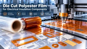
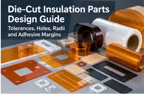
Die-cut electrical insulation parts are custom-shaped components produced from insulating films, sheets, tapes or laminates.
They are used to provide electrical separation, surface protection, mechanical spacing or other application-specific functions in electronic and electrical equipment.
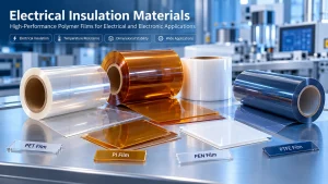
Common materials include:
- Polyethylene terephthalate (PET) film
- Polyimide (PI) film
- Polyphenylene sulfide (PPS) film
- Polyethylene naphthalate (PEN) film
- Polytetrafluoroethylene (PTFE) film
- Mica-based insulation sheets
- Selected adhesive-backed insulating laminates
Depending on the design, finished parts may include circular holes, elongated slots, rectangular windows, internal cutouts, rounded corners, tabs and pressure-sensitive adhesive layers.
Typical Part Types
Examples include:
- Battery module insulation liners
- Busbar insulation covers
- Electrical isolation washers
- Die-cut insulating spacers
- Power electronics barriers
- PCB assembly insulation pieces
- Adhesive-backed protective films
- Custom insulation gaskets
The material provides the required electrical, thermal or mechanical properties, while the die-cut geometry allows it to fit into the finished assembly.
For a broader overview of manufacturing options, visit our Precision Converting Services.
2. Key Design Features to Define Before Die Cutting
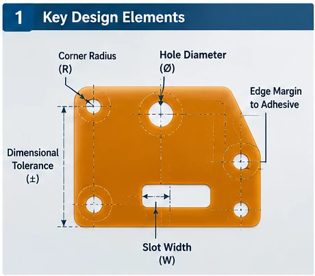
A complete insulation part drawing should define more than the external outline.
The following features can directly affect manufacturing feasibility.
| Design Feature | What to Specify | Why It Matters |
|---|---|---|
| Overall dimensions | Length, width and profile | Determines fit and material usage |
| Material thickness | Nominal thickness and tolerance | Affects cutting, flexibility and insulation |
| Hole diameter | Diameter and position | Controls alignment and assembly |
| Slot dimensions | Width, length and end shape | Influences tooling and mechanical stress |
| Corner radius | Internal and external radii | Helps manage cutting and tearing |
| Edge distance | Distance from features to outer edge | Affects strength and cutting stability |
| Adhesive coverage | Full coverage or selective areas | Controls bonding and electrical design |
| Release liner | Type, thickness and split configuration | Affects handling and installation |
| Critical dimensions | Functional tolerances and datums | Supports inspection and process control |
| Finished presentation | Individual pieces, sheets or rolls | Influences production and packing |
Functional Dimensions vs Non-Critical Dimensions
Not every dimension requires the same tolerance.
A hole that aligns with a locating pin may be critical to assembly.
An external edge that does not contact another component may allow a wider tolerance.
Engineers should identify functional dimensions and apply tighter tolerances only where necessary.
This approach can reduce tooling complexity, inspection effort and manufacturing cost.
Datum-Based Dimensioning
For parts containing multiple holes or cutouts, consider defining dimensions from common datums rather than creating long chains of dimensions.
Datum-based dimensioning can help control the position of critical features relative to the assembly.
Where appropriate, use a recognized geometric dimensioning and tolerancing system and specify the applicable drawing standard.
Design recommendation: Clearly identify which features control electrical clearance, alignment, mounting or sealing. These should receive priority during manufacturing feasibility review.
3. Dimensional Tolerances: How Tight Should They Be?
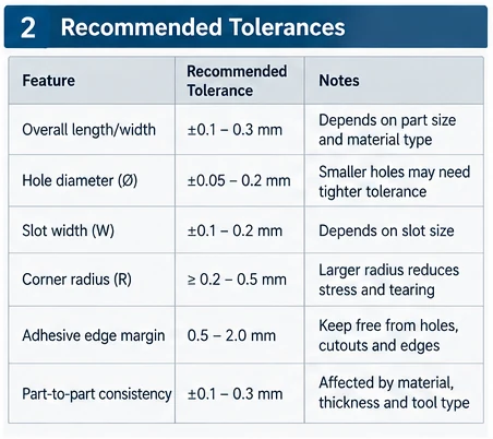
Dimensional tolerance is one of the most important considerations in precision die cutting.
However, there is no single tolerance that applies to every insulation film, thickness, part size or cutting method.
Achievable tolerance depends on:
- Material type
- Film thickness
- Part dimensions
- Tooling design
- Cutting process
- Material stretch and dimensional stability
- Temperature and humidity
- Adhesive and liner construction
- Measurement method
- Production volume
Why Very Tight Tolerances Can Increase Cost
Tighter tolerances may require:
- More precise tooling
- Additional process development
- Slower production
- More frequent inspection
- Greater material waste
- Additional quality controls
Therefore, applying the tightest possible tolerance to every feature is rarely the most economical approach.
Illustrative Tolerance Discussion
The following examples show how engineers might classify dimensional requirements during an RFQ review.
They are not guaranteed manufacturing capabilities or universal industry standards.
| Feature | Example Tolerance for Discussion | Engineering Consideration |
|---|---|---|
| Overall length or width | ±0.20 mm | May be suitable for initial feasibility discussion |
| Hole diameter | ±0.10 mm | Depends on hole size, material and tooling |
| Slot width | ±0.15 mm | Small slots may require additional evaluation |
| Hole-to-hole position | ±0.15 mm | Datum selection and inspection method matter |
| Critical alignment feature | Drawing-specific | May require special tooling or process validation |
| Adhesive registration | Drawing-specific | Depends on coating or lamination construction |
These example values must not be interpreted as a quotation, process guarantee or confirmation of HighTemp Material’s achievable tolerances.
Tolerance Stack-Up
When a part contains several related features, accumulated dimensional variation may affect the final assembly.
For example, a component with multiple holes may require hole-position control relative to a common datum rather than independent edge-to-hole dimensions.
A tolerance stack-up review is especially useful for parts installed around screws, locating pins, terminals or busbars.
How to Specify Tolerances on Your Drawing
For efficient quotation and inspection:
- State the units, preferably millimeters for metric projects.
- Identify critical dimensions.
- Define relevant datums.
- Specify individual tolerances where needed.
- Provide a general tolerance note for non-critical dimensions.
- Clarify whether dimensions apply to the base film or the complete laminate.
- Agree on the measurement method and inspection conditions.
Engineering takeaway: Tolerances should be driven by functional requirements and validated process capability, not selected from a generic chart.
4. Hole, Slot and Internal Cutout Design
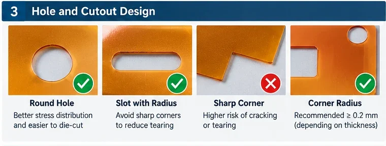
Holes and internal cutouts are common features in die-cut insulation components.
They may be required for screws, mounting points, terminals, connectors or alignment.
However, small or closely spaced features can introduce manufacturing challenges.
Minimum Hole Diameter
There is no universal minimum hole diameter for every die-cut material.
Feasibility depends on the material thickness, cutting method, tool geometry and the amount of material surrounding the hole.
Very small holes may cause:
- Incomplete cutting
- Difficulty removing waste material
- Edge distortion
- Tool wear
- Dimensional inconsistency
When possible, avoid specifying holes smaller than the assembly actually requires.
Hole-to-Edge Distance
The material remaining between a hole and the outer edge is sometimes called the ligament or edge web.
A narrow ligament can tear during cutting, waste removal, handling or installation.
The minimum acceptable distance depends on:
- Film thickness
- Material toughness
- Hole size
- Applied load
- Part orientation
- Cutting and stripping process
A useful preliminary design question is whether the remaining material can survive both manufacturing and the intended assembly process.
Do not assume that a fixed edge-distance rule applies to every PET, PI or PTFE part.
Hole-to-Hole Spacing
Closely spaced holes can create narrow material bridges.
These bridges may be vulnerable to tearing, especially when the part is removed from a release liner or positioned manually.
Where possible, increase spacing or revise the layout to maintain sufficient material between features.
Slot Design
Slots are often used for positioning adjustment, connector clearance or mechanical movement.
Rounded slot ends are generally preferable to sharp-ended slots because they avoid acute internal corners and may be easier to produce with certain tooling methods.
Specify:
- Slot width
- Overall slot length
- End radius
- Slot position
- Critical alignment tolerance
Internal Cutouts and Waste Removal
Large internal windows may be straightforward to cut, but narrow openings and complicated cutout shapes can create waste-removal challenges.
A part may require an additional process step if internal waste remains attached or is difficult to separate cleanly.
For production quotations, provide the full geometry rather than only the overall part dimensions.
5. Corner Radii: Why Sharp Corners Can Be a Problem
Corner geometry influences both manufacturing and the durability of finished insulation parts.
External Corners
Sharp external corners may be acceptable for some materials and applications.
However, rounded corners can improve handling and reduce the likelihood of snagging or lifting during installation.
For adhesive-backed parts, rounded external corners may also help reduce the risk of peeling initiated at a sharp point.
Internal Corners
Sharp internal corners can create stress concentrations.
Depending on the material and load direction, these features may become locations where tearing or cracking begins.
Adding a radius may improve mechanical robustness and simplify cutting.
How Large Should the Corner Radius Be?
There is no universal minimum corner radius for all die-cut insulation films.
The appropriate radius depends on:
- Material thickness
- Polymer type
- Film orientation
- Cutting method
- Tool geometry
- Part dimensions
- Mechanical loading
As an initial design practice, use the largest radius compatible with the assembly wherever sharp corners are not functionally necessary.
For example, a designer might investigate whether a 0.5 mm radius can replace a sharp internal corner, but that value is only an illustrative design option—not a validated minimum.
When Sharp Corners Are Unavoidable
If a sharp internal corner is functionally necessary, communicate this requirement during the RFQ stage.
The manufacturer may need to evaluate alternative cutting methods, tooling geometry or inspection requirements.
Design recommendation: Do not add small radii arbitrarily. Define the radius in the drawing and verify that it does not interfere with mating components.
6. Adhesive Edge Margins and Selective Adhesive Design
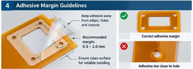
Adhesive-backed insulation parts introduce additional design considerations.
A typical construction may include:
- Electrical insulation film
- Pressure-sensitive adhesive
- Release liner
Depending on the product, the adhesive may cover the entire film or only selected regions.
What Is an Adhesive Edge Margin?
An adhesive edge margin is a defined distance between the adhesive boundary and a nearby feature, such as the outer edge, a hole or an internal cutout.
A recessed adhesive pattern may be used to:
- Reduce unwanted adhesive exposure
- Limit adhesive squeeze-out
- Keep selected electrical contact areas free of adhesive
- Improve handling and liner removal
- Control adhesive placement near holes or windows
However, edge margins are not always necessary.
In some applications, full-surface adhesive coverage is preferred.
Should Adhesive Extend to the Part Edge?
The answer depends on the application.
Full-edge coverage may maximize available bonding area, while a recessed adhesive pattern can help control exposed adhesive.
The appropriate design depends on:
- Substrate material
- Surface energy
- Adhesive chemistry
- Adhesive thickness
- Bonding pressure
- Temperature exposure
- Required peel strength
- Electrical and contamination requirements
How Much Adhesive Margin Is Needed?
There is no universal minimum margin.
For preliminary discussions, engineers may investigate whether an adhesive setback such as 0.5–2.0 mm is appropriate for a particular geometry.
This is an illustrative design range only, not a standard or guaranteed process capability.
The final margin must be determined from adhesive registration capability, die-cutting tolerances, component geometry and functional requirements.
Adhesive Around Holes and Cutouts
Adhesive near a mounting hole may transfer to fasteners, tooling or mating surfaces if the construction is not controlled.
Where a clean opening is required, specify whether adhesive must be:
- Flush with the film opening
- Recessed from the opening
- Absent within a defined zone
Also specify the allowable adhesive registration tolerance.
Release Liner Design
The release liner can significantly affect assembly efficiency.
Possible options include:
- Single-piece liner
- Split liner
- Extended liner tab
- Kiss-cut liner
- Individual part presentation
- Sheet or roll presentation
A liner tab may make small adhesive-backed insulation parts easier to handle without touching the adhesive.
Full Cut vs Kiss Cut
A full cut passes through the intended material stack.
A kiss cut is designed to cut selected layers while leaving a backing liner intact.
For adhesive-backed parts, kiss cutting may allow finished components to remain on the liner for efficient handling or automated placement.
The correct cutting depth and liner construction must be validated.
7. Material and Thickness Selection for Die-Cut Insulation Parts
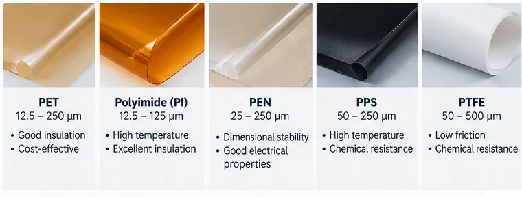
Material selection and geometry should be evaluated together.
Different insulation films behave differently during cutting, handling and assembly.
| Material | General Characteristics | Design Considerations |
|---|---|---|
| PET Film | Electrical insulation, dimensional consistency, cost-effective options | Thermal limits, edge quality, flexibility |
| Polyimide (PI) Film | High-temperature electrical insulation, thin flexible construction | Film grade, bending, adhesive compatibility |
| PPS Film | Thermal and chemical resistance | Thickness, stiffness, cutting behavior |
| PEN Film | Dimensional stability, selected thermal advantages | Film grade, forming and dimensional tolerance |
| PTFE Film | Chemical resistance and low friction | Creep, softness, cutting stability, bonding difficulty |
| Mica Sheet or Composite | Electrical insulation and high-temperature performance | Brittleness, binder system, edge integrity |
PET Die-Cut Insulation Parts
PET is widely considered for electrical barriers, battery liners and protective components where the selected grade meets the electrical and thermal requirements.
Thin PET films may be flexible and suitable for intricate parts, but very small features can still require process evaluation.
Polyimide Die-Cut Parts
PI film is often considered where elevated-temperature performance is important.
It can be used for electrical insulation around power electronics, electronic assemblies and selected battery components.
For more background, see our PI vs PET Film Comparison Guide.
PPS and PEN Films
PPS and PEN may be considered where their specific thermal, mechanical or dimensional properties provide an advantage.
The material grade, available thickness and actual cutting behavior should be confirmed before design approval.
PTFE Die-Cut Components
PTFE provides useful chemical resistance and low-friction characteristics.
However, its mechanical behavior, creep characteristics and surface properties can affect dimensional stability and adhesive bonding.
PTFE should not be treated as a direct substitute for PET or PI solely on the basis of electrical insulation performance.
Why Thickness Matters
Thickness can influence:
- Part stiffness
- Bend radius
- Edge quality
- Tooling requirements
- Dimensional stability
- Handling and installation
- Electrical insulation performance
For example, a 25 μm film and a 250 μm film may require different tooling and handling methods even when they share the same outer geometry.
The appropriate material and thickness must satisfy both the functional design and manufacturing requirements.
8. Die-Cutting Methods, Tooling and Production Feasibility
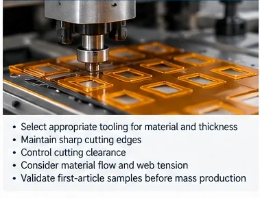
Different cutting methods may be suitable for different materials, part geometries and production volumes.
Steel-Rule Die Cutting
Steel-rule dies may be suitable for many sheet-based parts and certain production requirements.
Their suitability depends on the material, thickness, feature size and required tolerances.
Rotary Die Cutting
Rotary die cutting may be considered for repeat production of suitable flexible materials, especially when supplied in roll form.
Potential advantages include efficient continuous processing and compatibility with liner-based constructions.
However, tooling investment and web-handling requirements must be evaluated.
Digital or Alternative Cutting Methods
For prototypes or complex geometries, alternative cutting methods may be considered where appropriate.
Each process has different limitations regarding edge quality, material compatibility, speed and dimensional accuracy.
Tooling Cost vs Unit Cost
Tooling selection should consider both initial cost and production economics.
For low-volume prototypes, minimizing tooling investment may be important.
For repeat high-volume production, a dedicated tool may improve process consistency and unit economics.
First Article Inspection
Before volume production, first-article samples should be reviewed against the approved drawing.
Inspection may include:
- Overall dimensions
- Hole and slot dimensions
- Critical feature positions
- Corner radii
- Edge condition
- Adhesive placement
- Liner configuration
- Visual defects
First-article approval should also confirm whether the selected material and construction meet the intended assembly requirements.
HighTemp Material offers Custom Die Cutting Services for suitable insulation films and related materials, subject to technical evaluation.
9. Applications: Battery, PCB, Power Electronics and Industrial Equipment
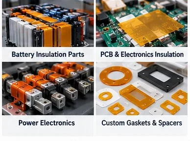
Die-cut insulation parts are used across many industries, but their design priorities differ.
Battery Module and Busbar Insulation
Battery applications may require custom liners, busbar covers and protective barriers.
Key design considerations include:
- Electrical clearance and coverage
- Mechanical abrasion
- Hole positioning
- Assembly handling
- Thermal exposure
- Flame-retardant requirements
- Material traceability
For flame-retardant PET applications, the exact material grade and certified thickness should be verified.
PCB and Electronic Assemblies
Electronic assemblies may use die-cut films for electrical isolation, component protection and spacing.
Critical features may include connector windows, mounting holes and alignment cutouts.
Designers should also consider processing temperature, soldering-related exposure and compatibility with the finished assembly.
Power Electronics and Inverters
Power electronic equipment may require insulation barriers around conductive components, heat sinks or housings.
Selection should consider electrical stress, thermal cycling, vibration and the possibility of contact with sharp metal edges.
Industrial Insulation Gaskets and Spacers
Some applications require custom gaskets, washers or spacers made from electrically insulating materials.
These components may need additional mechanical stiffness, chemical resistance or dimensional stability.
For related high-temperature insulation options, explore our Mica Sheet and Die-Cut Mica Gasket page.
10. Common Design Mistakes That Increase Cost or Cause Manufacturing Problems
Mistake 1: Applying Extremely Tight Tolerances to Every Dimension
This can increase inspection and tooling requirements without improving functionality.
Better approach: Identify critical features and allow practical tolerances elsewhere.
Mistake 2: Using Very Small Holes Without Checking Feasibility
Small holes may be difficult to cut and strip consistently.
Better approach: Review minimum feature size with the manufacturer before finalizing the drawing.
Mistake 3: Leaving Very Narrow Material Bridges
Insufficient material between holes or cutouts can lead to tearing.
Better approach: Increase edge distance or revise the geometry where possible.
Mistake 4: Using Sharp Internal Corners Unnecessarily
Sharp corners can create stress concentrations and manufacturing challenges.
Better approach: Add functional radii where permitted by the assembly.
Mistake 5: Failing to Define Adhesive Coverage
A drawing that only shows the insulation film outline may not fully describe the adhesive construction.
Better approach: Provide a separate adhesive pattern or clearly specify full coverage.
Mistake 6: Ignoring the Release Liner
Small adhesive-backed parts may be difficult to handle if the liner design is unsuitable.
Better approach: Confirm liner tabs, split liners and finished-part presentation.
Mistake 7: Specifying Material Thickness Without Tolerance
Nominal thickness alone may not adequately define the finished component.
Better approach: State the material grade and applicable thickness tolerance.
Mistake 8: Sending Only a Screenshot for Quotation
Screenshots often omit scale, dimensions, tolerances and material details.
Better approach: Supply a dimensioned PDF drawing and an editable CAD file where available.
11. RFQ Drawing Checklist for Custom Die-Cut Insulation Parts
A clear RFQ package helps suppliers evaluate technical feasibility and provide more accurate quotations.
| Item | Recommended Information |
|---|---|
| Part identification | Part number and revision |
| Material | Polymer type and required grade |
| Thickness | Nominal thickness and tolerance |
| Overall geometry | Dimensioned drawing |
| Critical features | Holes, slots, windows, radii |
| Dimensional tolerances | General and critical tolerances |
| Adhesive | Type, thickness, coverage pattern |
| Release liner | Type, tabs, split configuration |
| Electrical requirements | Applicable dielectric and insulation specifications |
| Temperature requirements | Continuous and peak exposure |
| Certifications | Required material-level documentation |
| Quantity | Prototype and annual production volumes |
| Delivery format | Individual parts, sheets or rolls |
| Inspection | First-article and ongoing quality requirements |
Recommended Files for Quotation
Where available, send:
- A dimensioned PDF drawing
- A DXF, DWG or other suitable CAD file
- A material specification or existing TDS
- An adhesive coverage drawing if applicable
- An assembly image showing how the part will be used
- The required annual quantity and sample schedule
The drawing should clearly distinguish between mandatory requirements and preferences that may be adjusted for manufacturability.
Design for Manufacturing Review
Before approving tooling, request a review of:
- Feature feasibility
- Material suitability
- Cutting method
- Tolerance capability
- Adhesive registration
- Waste removal
- Part presentation
- Inspection approach
Early design review can reduce the risk of repeated tooling changes and unexpected production costs.
12. Custom Die-Cut Insulation Parts from HighTemp Material
HighTemp Material focuses on high-temperature electrical insulation films and precision-converted components for industrial applications.
Our relevant product and service areas include:
- PET electrical insulation films
- Polyimide insulation films
- PPS and PEN films
- Custom film slitting
- Precision die-cut components
- Adhesive-backed insulation constructions
- Drawing-based material and processing evaluation
We can discuss suitable material options, available thicknesses, part geometry, converting feasibility and documentation requirements based on your project.
Request a Custom Die-Cut Insulation Parts Quote
Are you developing a battery insulation liner, busbar cover, electronic insulation spacer or adhesive-backed protective component?
Send us your drawing, material requirements, thickness, critical tolerances and estimated production quantity.
We can review the project and discuss potential manufacturing approaches.
Contact HighTemp Material to request a quotation or discuss your design.
Frequently Asked Questions
What tolerances can be achieved for die-cut insulation parts?
Achievable tolerances depend on the material, thickness, part geometry, tooling and cutting process. A supplier should confirm tolerances for the specific drawing rather than relying on a universal tolerance value.
What is the minimum hole size for die-cut PET or PI film?
There is no single minimum hole size that applies to all PET or PI films. The practical limit depends on material thickness, tooling, hole spacing and waste-removal requirements.
Why should internal corners have a radius?
Rounded internal corners can reduce stress concentration and may improve cutting and handling performance. The appropriate radius depends on the material and part geometry.
How much adhesive edge margin should I leave?
The required margin depends on adhesive coverage, registration tolerance, hole geometry and assembly requirements. A preliminary margin may be considered during design review, but the final dimension should be confirmed with the converter.
Can adhesive-backed insulation films be kiss-cut?
Yes, many suitable adhesive-backed constructions can be kiss-cut so the finished parts remain on a release liner. The process must be validated for the actual film, adhesive and liner.
Is rotary die cutting better than flatbed die cutting?
Neither method is universally better. Rotary die cutting can be attractive for suitable repeat roll-fed production, while flatbed or alternative cutting methods may be more appropriate for other part sizes, materials or quantities.
Can the same die-cut design be used for PET and PI films?
Sometimes, but a material change may affect cutting behavior, stiffness, shrinkage, edge quality and finished-part performance. A material substitution should be reviewed and validated.
What files should I send for a die-cut insulation parts quotation?
A dimensioned PDF drawing, an editable CAD file if available, material and thickness requirements, adhesive details, critical tolerances and estimated quantities are recommended.
Conclusion
Reliable die-cut insulation parts begin with good engineering design.
Dimensions, tolerances, hole sizes, edge distances, corner radii and adhesive margins all influence how consistently a part can be manufactured and how well it performs in the final assembly.
Rather than applying generic design rules to every material, engineers should define functional requirements and work with the converter to validate process capability.
For PET, PI, PPS, PEN and other electrical insulation materials, early design-for-manufacturing review can help improve part quality, control cost and reduce unnecessary tooling revisions.
HighTemp Material supports material selection and precision converting discussions for custom electrical insulation components.
Request a Die-Cut Insulation Parts Quote
Technical note: Dimensional tolerances, radii and adhesive margins discussed in this guide are preliminary design considerations. They are not universal manufacturing standards or confirmed HighTemp Material process capabilities. Final requirements must be agreed through drawing review, tooling evaluation, first-article inspection and application testing.