




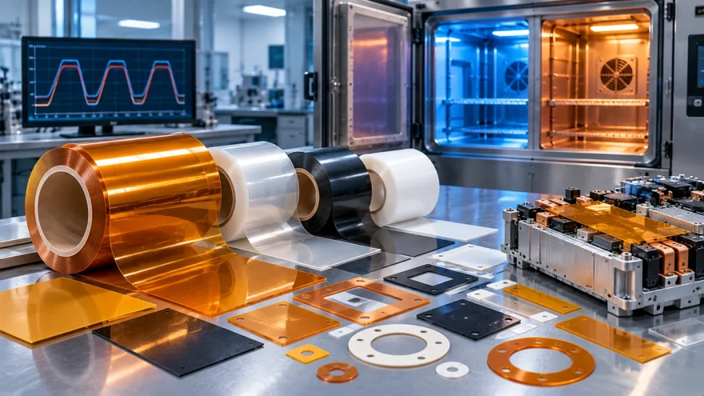
An Engineering Guide to Dimensional Stability, CTE Mismatch, Material Aging and Reliability Testing
A polymer film may perform well during a single high-temperature exposure yet behave differently after hundreds or thousands of heating and cooling cycles.
In batteries, power electronics, PCB assemblies and industrial electrical equipment, insulation materials rarely experience perfectly constant temperatures. Instead, they may undergo repeated changes caused by equipment startup and shutdown, operating loads, environmental conditions or manufacturing processes.
These changes can affect dimensional stability, adhesion, mechanical integrity and, in some cases, the electrical reliability of an insulation system.
For engineers and technical buyers, the central question is not simply:
“What is the maximum temperature this film can withstand?”
A more useful question is:
“Will this material and its complete insulation construction maintain the required performance after repeated exposure to the application’s actual temperature profile?”
This guide explains how thermal cycling affects high-temperature polymer films, compares important material-selection considerations for PI, PET, PPS, PEN and PTFE, and outlines practical testing and qualification methods.
1. Why Thermal Cycling Matters for Electrical Insulation
Electrical insulation materials often serve several functions simultaneously.
They may provide:
- Electrical separation between conductive components
- Protection against abrasion or mechanical contact
- Dimensional barriers around terminals and busbars
- Flexible insulation between moving or expanding components
- Support for adhesive-backed insulation assemblies
- Protection during selected manufacturing operations
An insulation film must therefore maintain more than its initial dielectric properties.
For example, a battery insulation liner may have adequate dielectric strength when new. However, if repeated thermal expansion causes it to shift, curl or tear, the installed insulation coverage may no longer match the original design.
Similarly, a film bonded to an aluminum or copper component may experience stress because the polymer, adhesive and metal expand at different rates.
Thermal cycling reliability is a property of the material, its geometry, its interfaces and its installed environment—not just the polymer name.
2. What Is Thermal Cycling?
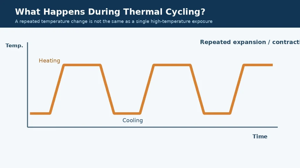
Thermal cycling is the repeated exposure of a material or assembly to changing temperatures.
A typical cycle includes:
- Exposure to a lower temperature
- Heating toward a higher temperature
- A defined dwell at the higher temperature
- Cooling toward the lower temperature
- A defined dwell at the lower temperature
The exact sequence depends on the test method and application.
Thermal Cycling vs Thermal Aging
Thermal aging generally evaluates the effects of exposure to elevated temperature over time.
Thermal cycling introduces repeated temperature changes that may create expansion, contraction and interface stresses.
These tests investigate related but different failure mechanisms.
| Factor | Thermal Aging | Thermal Cycling |
|---|---|---|
| Main exposure | Elevated temperature over time | Repeated temperature changes |
| Typical concern | Chemical or physical aging | Expansion mismatch and cyclic stress |
| Potential effects | Embrittlement, oxidation, property changes | Curling, fatigue, cracking, delamination |
| Important variables | Temperature, duration, atmosphere | Temperature limits, ramp rate, dwell, cycles |
| Qualification value | Long-term heat exposure assessment | Temperature-change durability assessment |
Thermal cycling does not replace long-term aging evaluation. In demanding applications, both may be needed.
Thermal Cycling vs Thermal Shock
Thermal shock generally refers to relatively rapid temperature changes that can generate significant transient temperature gradients.
A slower thermal cycling test may allow more time for the specimen to approach temperature equilibrium.
The terms should not be used interchangeably without defining the test profile.
The applicable test method and severity must be specified.
3. Coefficient of Thermal Expansion (CTE) and Interfacial Stress
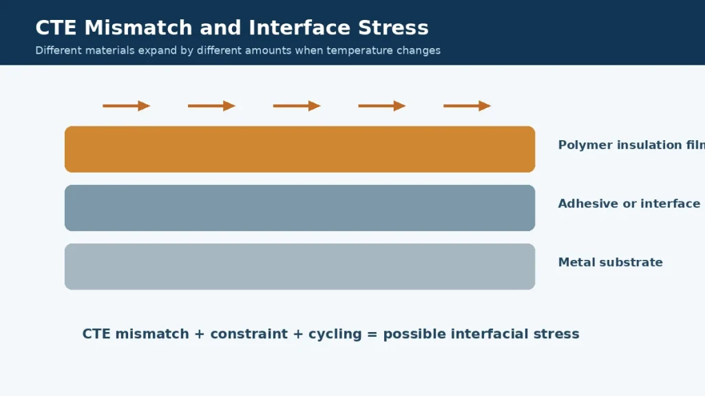
One of the most important mechanisms behind thermal cycling damage is the mismatch in thermal expansion between materials.
What Is CTE?
The coefficient of thermal expansion (CTE) describes how a material’s dimensions change with temperature.
For a simple linear approximation:
ΔL = α × L₀ × ΔT
Where:
- ΔL = change in length
- α = linear coefficient of thermal expansion
- L₀ = initial length
- ΔT = temperature change
This equation is a simplified approximation for a material under suitable conditions. Real polymer films may exhibit nonlinear, anisotropic or time-dependent behavior.
Why CTE Mismatch Matters
Consider a thin insulation film bonded to a metal substrate.
When temperature rises, the film and metal may attempt to expand by different amounts.
Because the materials are bonded, their movement is constrained.
This can generate mechanical stress within the film, adhesive or interface.
Repeated cycles may contribute to:
- Adhesive edge lifting
- Delamination
- Local wrinkling
- Film distortion
- Stress around holes and cutouts
- Loss of dimensional accuracy
The risk depends on the complete material system.
A Simple Engineering Example
Suppose two hypothetical materials have linear CTE values of 20 and 50 ppm/K.
For a temperature change of 100 K, the difference in their unconstrained thermal strain would be approximately:
(50 − 20) × 10⁻⁶ × 100 = 0.003, or 0.3%.
For a nominal 100 mm length, that corresponds to a difference in free thermal expansion of approximately 0.3 mm.
This is only an illustrative calculation, not a prediction of actual bonded-part displacement or failure.
The real stress depends on stiffness, geometry, bonding, relaxation and temperature-dependent properties.
Film Orientation and Anisotropy
Some polymer films are manufactured through stretching or orientation processes.
Their properties may differ between the machine direction (MD) and transverse direction (TD).
For precision insulation components, this can affect:
- Thermal shrinkage
- Dimensional change
- Curling
- Die-cut tolerance stability
- Hole positioning
Where dimensional stability is critical, request grade-specific MD and TD data rather than assuming identical behavior in both directions.
4. Common Failure Modes During Thermal Cycling
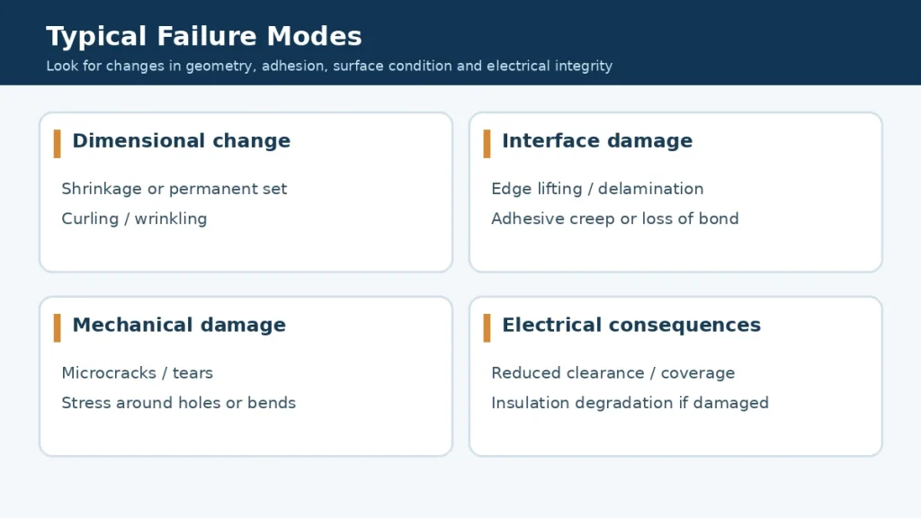
Thermal cycling can contribute to several distinct failure mechanisms.
Not every material will experience every failure mode, and visible damage does not always indicate the full extent of property change.
4.1 Dimensional Shrinkage or Permanent Set
Some polymer films may exhibit irreversible dimensional change after thermal exposure.
This can result from relaxation of manufacturing-induced orientation, material morphology changes or other temperature-dependent processes.
Consequences may include:
- Misaligned holes
- Reduced insulation coverage
- Distorted die-cut profiles
- Changes in assembly fit
4.2 Curling and Wrinkling
A free-standing film may curl due to residual stress or uneven dimensional changes.
Laminated structures may wrinkle when adjacent layers respond differently to temperature.
Curling can complicate automated placement or reduce contact with the intended surface.
4.3 Cracking and Tearing
Repeated mechanical stress may contribute to cracking or tearing, particularly around:
- Sharp internal corners
- Narrow material bridges
- Mounting holes
- Fold lines
- Edges contacting rigid components
Material toughness, thickness, orientation and assembly constraints all influence the outcome.
4.4 Adhesive Delamination
Adhesive-backed insulation parts may experience interface stress as temperatures change.
Potential symptoms include:
- Edge lifting
- Bubbles
- Partial debonding
- Reduced peel adhesion
- Adhesive creep
- Residue or transfer
Adhesive performance should be evaluated after the actual thermal exposure, not only at room temperature before testing.
4.5 Changes in Electrical Insulation Performance
Electrical reliability may be affected if cycling causes physical damage, reduced coverage, moisture-related effects or changes in the complete insulation construction.
However, thermal cycling does not automatically reduce dielectric strength in every polymer film.
Electrical testing is needed to determine whether the required performance has changed.
4.6 Surface and Interface Damage
Microcracks, abrasion, contamination or coating separation may occur in certain constructions.
Inspection should consider both the film itself and any adhesive, primer, coating or reinforcement layers.
5. Thermal Cycling, Thermal Aging and Material Properties
The response of an insulation film depends on several interconnected properties.
Glass Transition and Temperature-Dependent Behavior
The glass transition temperature (Tg) is relevant to the mechanical response of many polymer materials.
As temperature changes, stiffness and viscoelastic behavior may also change.
However, Tg alone does not define a film’s maximum service temperature or thermal cycling capability.
Polymer morphology, crystallinity, reinforcement, processing history and formulation must also be considered.
Modulus and Flexibility
A stiffer material may resist deformation in some configurations but may also transmit higher stresses when constrained.
A more compliant material may accommodate movement but could experience creep or dimensional instability.
Neither stiffness nor flexibility alone determines reliability.
Creep and Stress Relaxation
At elevated temperatures, polymers and adhesives may deform over time under sustained load.
During repeated heating and cooling, creep and stress relaxation can alter the distribution of stress in an assembly.
This is particularly relevant to clamped, bonded or mechanically loaded insulation parts.
Moisture and Environmental Exposure
Humidity, condensation and chemical exposure can interact with temperature cycling.
For some materials, moisture may influence mechanical, dimensional or electrical behavior.
The qualification plan should represent the real service environment rather than testing temperature in isolation when other conditions are important.
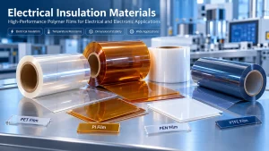
6. PI vs PET vs PPS vs PEN vs PTFE: Thermal Cycling Selection Considerations
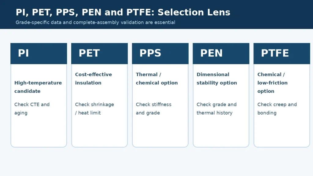
Material selection should be based on the exact film grade and application.
The following table summarizes useful engineering considerations without assigning universal cycle-life rankings.
| Material | Potential Advantages | Important Thermal Cycling Questions |
|---|---|---|
| Polyimide (PI) | High-temperature capability in suitable grades; flexible insulation | What are the grade-specific CTE, shrinkage and aging properties? |
| PET | Widely available, economical electrical insulation | Is the maximum temperature within the qualified range? Is orientation-related shrinkage acceptable? |
| PPS | Useful thermal and chemical resistance in suitable grades | How do stiffness, crystallinity and processing history affect dimensional stability? |
| PEN | Potential dimensional and thermal advantages over some PET grades | Are MD/TD stability and thermal exposure data available for the exact grade? |
| PTFE | Chemical resistance and low-friction performance | Are creep, high thermal expansion and bonding challenges acceptable? |
Polyimide (PI) Film
Polyimide film is frequently considered for demanding electrical insulation applications involving elevated temperatures.
Its suitability for thermal cycling depends on:
- Film chemistry and grade
- Thickness
- Thermal expansion
- Mechanical constraints
- Exposure duration
- Adhesive construction
- Required electrical properties
Some specialized PI films are engineered for improved dimensional stability, but it would be incorrect to assume that every PI grade behaves identically.
For material background, see our PI vs PET Film Comparison Guide.
PET Film
PET is widely used in electrical insulation because of its balance of properties, availability and cost.
However, its thermal limitations and dimensional behavior must be assessed for the intended service conditions.
In particular, oriented PET films may exhibit heat-related dimensional change that depends on grade and processing history.
For applications with repeated elevated-temperature exposure, request shrinkage and aging data for the actual PET grade.
PPS Film
PPS film may be considered where higher-temperature or chemical-resistance requirements exceed the capabilities of a particular PET grade.
Its thermal cycling behavior depends on film construction, crystallinity, thickness and mechanical constraints.
Engineers should examine dimensional stability and mechanical performance rather than relying solely on a published temperature limit.
PEN Film
PEN film may offer useful thermal and dimensional characteristics for selected electrical and industrial applications.
However, differences between film grades, orientation and thermal history can be significant.
For precision-cut components, request dimensional-change data in both principal film directions.
PTFE Film
PTFE offers excellent chemical resistance and low-friction characteristics for many applications.
Nevertheless, its relatively high thermal expansion, creep behavior and difficult-to-bond surface can create challenges in constrained or adhesive-backed constructions.
For applications involving PTFE, evaluate the complete geometry and attachment method.
Which Material Is Best?
There is no universal best polymer for all thermal cycling conditions.
A suitable material must satisfy:
- Temperature exposure limits
- Dimensional stability
- Mechanical integrity
- Electrical insulation requirements
- Interface compatibility
- Manufacturing feasibility
- Cost and supply requirements
A more expensive polymer does not automatically deliver a more reliable assembly if the main failure mechanism is poor bonding or unsuitable part geometry.
7. Why Adhesives, Coatings and Die-Cut Geometry Matter
A film that performs well as a free-standing specimen may behave differently when bonded, coated or die-cut.
Adhesive-Backed Insulation Films
A pressure-sensitive adhesive introduces another material with its own:
- Thermal expansion
- Modulus
- Glass transition behavior
- Creep resistance
- Adhesion properties
- Thermal aging characteristics
The adhesive may become the limiting component of the construction.
For high-temperature bonding, evaluate peel and shear properties after thermal cycling using the actual substrate.
Multilayer Insulation Laminates
A multilayer structure can combine useful material properties, but each interface introduces potential mismatch.
Layer thickness, bonding strength and stiffness influence how stress is distributed.
Testing the individual layers is useful but does not replace evaluation of the complete laminate.
Die-Cut Features
Holes, slots and sharp internal corners can concentrate mechanical stress.
Narrow bridges of material may be particularly sensitive to repeated movement or dimensional change.
Where practical, consider:
- Rounded internal corners
- Adequate edge distances
- Controlled hole positioning
- Avoidance of unnecessary narrow sections
- Proper support during installation
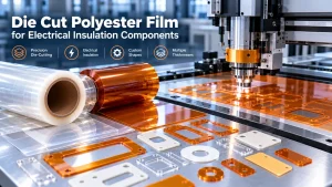
HighTemp Material supports drawing-based Custom Die Cutting and Precision Converting discussions for suitable insulation materials.
Roll Direction and Dimensional Stability
For converted film parts, the original machine direction may matter.
When thermal shrinkage or dimensional accuracy is critical, identify the orientation of the part relative to the source roll.
This information can support more consistent qualification and production.
8. How to Design a Thermal Cycling Test for Insulation Films
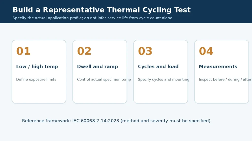
A useful test should reflect the intended application and produce measurable acceptance results.
Reference Standard: IEC 60068-2-14
IEC 60068-2-14:2023 addresses environmental testing involving changes of temperature.
It provides a framework for specified temperature-change tests, including the relevant exposure conditions and reporting requirements.
The appropriate method and severity must be selected for the specimen and application.
A generic statement such as “passed thermal cycling” is insufficient without the actual test conditions.
Step 1: Define the Temperature Limits
Specify the lowest and highest temperatures relevant to the application.
The limits should be based on actual operating, storage or qualification requirements.
Step 2: Define Ramp Rate or Transfer Conditions
Temperature change rate can influence transient gradients and stress.
A rapid transition may produce different results from a slow transition between the same temperature limits.
Step 3: Define Dwell Time
Dwell time determines how long the specimen remains exposed at each temperature condition.
The specimen’s temperature may lag behind the chamber temperature.
This is especially important for thick assemblies or parts attached to large metal components.
Step 4: Specify the Number of Cycles
Cycle count should reflect the relevant qualification plan.
There is no universal number of cycles that establishes long-term reliability for all electrical insulation films.
A test with a small number of cycles may screen for certain problems but cannot automatically predict years of service.
Step 5: Test the Actual Construction
Where possible, include representative:
- Film thickness
- Adhesive
- Metal substrate
- Die-cut geometry
- Mechanical constraints
- Installation method
Free-standing film specimens can provide useful screening data, but assembly testing is often necessary.
Step 6: Define Measurements and Acceptance Criteria
Depending on the application, measure:
| Property | Possible Evaluation |
|---|---|
| Dimensional stability | Length and width change; MD/TD shrinkage |
| Visual integrity | Cracks, wrinkles, edge lifting, bubbles |
| Adhesion | Peel or shear testing before and after cycling |
| Mechanical properties | Tensile strength, elongation or bend performance |
| Electrical properties | Dielectric withstand, insulation resistance |
| Geometry | Hole position, edge coverage, part flatness |
| Interface condition | Delamination, coating separation or damage |
Acceptance criteria should be established before testing.
Step 7: Record and Report Results
A useful report should include:
- Material identification and lot
- Specimen geometry
- Film and adhesive thickness
- Mounting conditions
- Temperature profile
- Ramp or transfer conditions
- Dwell times
- Number of cycles
- Measurements and inspection methods
- Failure observations
- Acceptance criteria
- Deviations from the specified procedure
Illustrative Test Profile
An engineering team might propose a preliminary profile such as:
- Lower temperature: −40°C
- Upper temperature: +125°C
- Dwell time: 30 minutes at each extreme
- Number of cycles: 500
- Inspection: before testing, at selected intervals and after completion
These values are hypothetical examples, not universal recommendations or a claim that any specific material is suitable for these conditions.
They must be adjusted to the product requirements, material limits and applicable qualification specification.
Can Thermal Cycling Predict Service Life?
Thermal cycling can help identify weaknesses and compare candidate constructions under defined conditions.
However, converting laboratory cycle counts into service years requires a validated relationship between the accelerated test and the actual field failure mechanism.
Without such validation, claims such as “500 cycles equals 10 years” are not technically justified.
9. Application-Specific Considerations
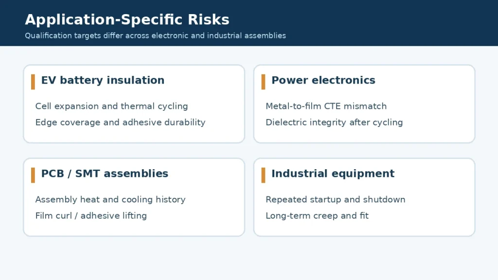
EV Battery Packs and Energy Storage
Battery insulation components may experience temperature changes during charging, discharging, storage and environmental exposure.
Important considerations include:
- Insulation coverage after dimensional change
- Adhesive durability
- Cell or module movement
- Mechanical abrasion
- Die-cut part positioning
- Electrical withstand after cycling
Material flammability classifications and electrical test results must be assessed separately from thermal cycling performance.
Power Electronics and Inverters
Power electronics may combine metal housings, busbars, polymer films and adhesive layers.
Differences in thermal expansion can create stress at interfaces.
For these applications, evaluate:
- Film-to-metal bonding
- Insulation clearance
- Thermal cycling under representative mounting conditions
- Vibration and mechanical loading
- Electrical properties after cycling
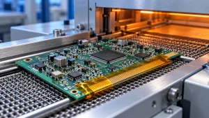
PCB and SMT Assemblies
Electronics manufacturing may expose temporary masking or insulation materials to heating and cooling processes.
Temporary process exposure and long-term installed service should be treated separately.
For masking materials, relevant criteria may include:
- Dimensional stability
- Edge lifting
- Adhesive residue
- Clean removal
- Surface contamination
Industrial Electrical Equipment
Motors, transformers, heating systems and other electrical equipment may undergo repeated startup and shutdown cycles.
The insulation system may need to accommodate expansion, contraction and mechanical loading.
Testing should reflect the actual installed condition.
10. How to Reduce Thermal Cycling Failure Risk
Several practical design strategies can help improve reliability.
Select the Material for the Full Temperature Profile
Do not select a film using only the highest temperature value.
Review the minimum temperature, maximum temperature, exposure duration and cycling frequency.
Reduce Unnecessary Constraint
A tightly constrained film may experience more stress than a component allowed to expand or contract.
Where functionally possible, accommodate differential movement in the design.
Match Materials and Interfaces Carefully
Evaluate the compatibility of the film, adhesive, substrate and any coating.
CTE mismatch does not automatically cause failure, but it should be considered alongside stiffness and bonding.
Optimize Part Geometry
Avoid unnecessary sharp corners, narrow bridges and unsupported edges.
Use drawing-based manufacturing review for critical die-cut components.
Validate Adhesive Constructions
For adhesive-backed parts, test the complete laminate after cycling.
Room-temperature adhesion data alone may not be sufficient.
Control Film Orientation
When relevant, define MD and TD orientation for precision-converted parts.
Specify Incoming Quality Requirements
For critical applications, consider requirements for:
- Material grade and lot traceability
- Thickness
- Dimensional stability
- Visual quality
- Adhesive construction
- Test documentation
Validate Before Volume Production
Prototype and first-article testing can help identify risks before tooling or production commitments increase.
11. Engineering RFQ and Qualification Checklist
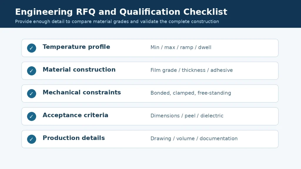
For projects involving repeated temperature changes, provide the following information when requesting material recommendations or quotations.
| Requirement | Information to Provide |
|---|---|
| Application | Battery, PCB, inverter, motor or industrial equipment |
| Insulation function | Electrical isolation, protective barrier or other |
| Material preference | PI, PET, PPS, PEN, PTFE or open to recommendation |
| Temperature range | Minimum and maximum temperatures |
| Temperature profile | Ramp rate, dwell time and number of cycles |
| Service life | Intended operating duration and duty cycle |
| Substrate | Metal, polymer, coated surface or composite |
| Mounting | Free-standing, clamped, bonded or mechanically fixed |
| Adhesive | Chemistry, thickness and coverage, if applicable |
| Geometry | Drawing, holes, slots, radii and critical dimensions |
| Film orientation | MD/TD requirements, if relevant |
| Electrical requirements | Dielectric and insulation test criteria |
| Mechanical requirements | Flexibility, tensile or abrasion performance |
| Documentation | TDS, test reports, declarations and traceability |
| Production | Sample quantity, annual volume and delivery format |
What Should You Ask a Supplier?
A useful technical RFQ should ask:
- Is the recommended material grade suitable for the specified temperature profile?
- Are thermal shrinkage or dimensional-change data available?
- Are the properties reported in MD and TD where relevant?
- Is there thermal cycling or aging data for the exact grade?
- Does the test cover a free-standing film or a bonded construction?
- Are adhesive and substrate compatibility tests required?
- Can the film be slit or die-cut to the specified tolerances?
- Which properties require customer-level qualification?
If test data is unavailable, request samples and agree on a validation plan rather than assuming the material has been qualified.
12. High-Temperature Film and Precision Converting Support
HighTemp Material supplies high-temperature electrical insulation materials and supports custom converting discussions for industrial applications.
Relevant material categories include:
- Polyimide (PI) films
- PET electrical insulation films
- PPS films
- PEN films
- PTFE films
- Selected adhesive-backed insulation materials
Relevant services include:
We can discuss material grade, thickness, part geometry, converting requirements and available documentation based on your application.
Request Material Selection Support
Are you developing an insulation component exposed to repeated heating and cooling?
Send us your operating temperature range, material requirements, assembly drawing, substrate information and estimated quantity.
Where thermal cycling qualification is required, please also provide the test profile and acceptance criteria.
Contact HighTemp Material to discuss suitable insulation film and converting options.
Frequently Asked Questions
What is thermal cycling in electrical insulation materials?
Thermal cycling is repeated exposure to changing temperatures. It can introduce dimensional changes, mechanical stress and interface loading that may affect an insulation material or assembly.
Is thermal cycling the same as thermal aging?
No. Thermal aging generally evaluates the effects of temperature exposure over time, while thermal cycling focuses on repeated temperature changes. Both may be necessary for reliability assessment.
Which insulation film is best for thermal cycling: PI, PET, PPS, PEN or PTFE?
There is no universal best material. The correct choice depends on temperature limits, dimensional stability, geometry, adhesive construction and required electrical and mechanical performance.
Does polyimide film shrink during thermal cycling?
Dimensional behavior depends on the specific PI grade, manufacturing process, orientation and test conditions. Grade-specific dimensional-change data should be reviewed.
Why do adhesive-backed insulation films delaminate during temperature cycling?
Potential causes include thermal expansion mismatch, adhesive creep, insufficient surface preparation, material aging or mechanical stress. Failure analysis should consider the complete construction.
What is CTE mismatch?
CTE mismatch occurs when adjacent materials expand or contract by different amounts as temperature changes. When constrained or bonded, this difference may generate mechanical stress.
What standard is used for thermal cycling testing?
IEC 60068-2-14:2023 is a relevant standard for environmental testing involving changes of temperature. The exact method and severity must be defined for the application.
How many thermal cycles should insulation film pass?
There is no universal cycle-count requirement for all films. The test should follow the relevant product specification and defined acceptance criteria.
Can thermal cycling reduce dielectric strength?
It can affect electrical reliability if cycling causes damage or other changes to the insulation system, but a reduction is not inevitable. Electrical testing before and after cycling is needed.
Can die-cut insulation parts be evaluated for thermal cycling?
Yes. Testing the finished geometry and installed construction can help identify issues that may not appear in free-standing film specimens.
Conclusion
Thermal cycling can affect high-temperature films and electrical insulation materials through dimensional change, CTE mismatch, mechanical stress, adhesive degradation and interface damage.
A material’s maximum temperature rating alone does not establish its thermal cycling reliability.
For PI, PET, PPS, PEN and PTFE films, engineers should evaluate the specific grade, thickness, geometry, adhesive construction and actual temperature profile.
The most reliable selection process combines material data, representative testing, clear acceptance criteria and design-for-manufacturing review.
HighTemp Material supports material selection and precision converting discussions for custom electrical insulation applications.
Request High-Temperature Insulation Material Support
Technical References
- IEC 60068-2-14:2023 — Environmental Testing, Test N: Change of Temperature
- IEC 60068-2-1 — Environmental Testing, Cold
- IEC 60068-2-2 — Environmental Testing, Dry Heat
- HighTemp Material — PI vs PET Film Comparison
Engineering disclaimer: This article provides general material-selection guidance. Illustrative temperature profiles, calculations and potential failure mechanisms are not product-specific test results or performance guarantees. Final material selection and qualification must be based on verified grade-specific data, applicable standards and testing of the intended assembly.