


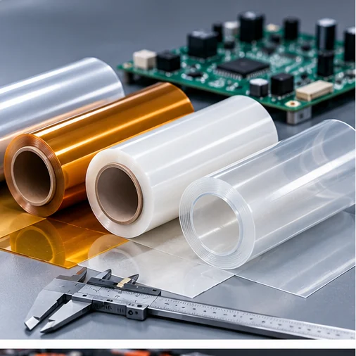
An Engineering Guide to PET, Polyimide, PPS and PEN Film Thickness Selection for Batteries, Power Electronics and Industrial Applications
Choosing the right electrical insulation film thickness is a critical step in designing reliable electronic and electrical assemblies.
A film that is too thin may not provide sufficient electrical or mechanical protection under actual operating conditions. A film that is unnecessarily thick may increase material cost, reduce flexibility, complicate assembly or consume valuable installation space.
However, selecting an insulation film is not simply a matter of choosing the thickest available material.
The correct electrical insulation film thickness depends on voltage requirements, dielectric breakdown performance, operating temperature, mechanical stress, environmental exposure and the properties of the specific material grade.
In this engineering guide, we explain how to evaluate insulation film thickness, compare commonly used PET, PI, PPS and PEN films, and provide practical selection considerations for battery packs, power electronics, PCB assemblies and industrial electrical equipment.
1. Why Electrical Insulation Film Thickness Matters
Electrical insulation films are used to prevent unintended electrical contact between conductive components.
They can be found in:
- EV battery modules and energy storage systems
- Busbar insulation
- Power electronics and inverters
- Motors and transformers
- Electronic assemblies
- Electrical isolation barriers
- Custom die-cut insulation components
Film thickness influences several important characteristics.
Electrical Performance
The thickness of an insulation layer affects the electric field across the material and can influence its breakdown voltage.
However, breakdown performance also depends on the material formulation, manufacturing quality, testing conditions and environmental exposure.
Mechanical Protection
An insulation film may need to withstand abrasion, bending, handling, assembly pressure or contact with sharp component edges.
In some applications, mechanical durability is a more important limitation than the initial dielectric breakdown voltage.
Flexibility and Assembly
Thinner films are often easier to bend, wrap and fit into compact spaces.
Thicker films may provide additional mechanical robustness but can create challenges around small bend radii or complex component geometries.
Thermal Performance
Material selection must account for continuous operating temperature, short-term thermal exposure and thermal aging.
Increasing thickness does not automatically make a polymer film suitable for a higher operating temperature.
Cost and Processing Efficiency
Thickness affects material consumption, roll yield, die-cutting behavior, winding stability and the final cost of an insulation component.
Engineering takeaway: The objective is to select the minimum practical thickness that satisfies all validated electrical, mechanical, thermal and manufacturing requirements—not simply the thinnest or thickest available film.
2. Common Electrical Insulation Film Thickness Options
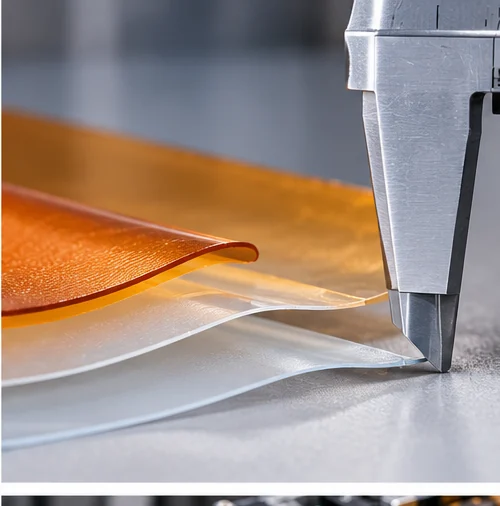
Electrical insulation films are available in a wide range of thicknesses, depending on the polymer, manufacturer and grade.
Common nominal thicknesses used in preliminary material selection include:
| Thickness | Equivalent in mm | Equivalent in mil | General Design Considerations |
|---|---|---|---|
| 12.5 μm | 0.0125 mm | 0.49 mil | Very thin, flexible insulation where the grade and handling process permit |
| 25 μm | 0.025 mm | 0.98 mil | Thin electrical barriers and compact insulation components |
| 50 μm | 0.050 mm | 1.97 mil | Balance of flexibility and handling robustness |
| 75 μm | 0.075 mm | 2.95 mil | Additional mechanical thickness for selected insulation designs |
| 100 μm | 0.100 mm | 3.94 mil | More substantial barriers where installation space allows |
| 125 μm | 0.125 mm | 4.92 mil | Stiffer insulation liners and shaped components |
| 188 μm | 0.188 mm | 7.40 mil | Thicker insulation components, subject to grade availability |
| 250 μm | 0.250 mm | 9.84 mil | Rigid or semi-rigid insulation barriers, depending on material |
| 350 μm | 0.350 mm | 13.78 mil | Specialized thicker constructions where available |
Note: These are illustrative nominal thickness options, not a universal stock list or an electrical performance ranking. Not every polymer or certified grade is available at every thickness.
Is 25 μm Electrical Insulation Film Thick Enough?
A 25 μm film may be suitable for certain electrical insulation applications, but its adequacy cannot be established from thickness alone.
Engineers must consider:
- Maximum electrical stress
- Required withstand test
- Film dielectric breakdown data
- Material defects and thickness tolerance
- Operating temperature
- Mechanical damage during installation
- Long-term environmental exposure
A 25 μm PI film and a 25 μm PET film may have different electrical and thermal properties.
Likewise, two 25 μm PET films from different manufacturers may not have identical dielectric performance.
Is 125 μm Film Always Safer Than 50 μm Film?
Not necessarily.
A thicker film can provide additional physical separation, but it may also introduce bending stress, poor conformity or assembly interference.
If a thicker film is forced around a sharp edge, the resulting mechanical damage may undermine the intended insulation protection.
The complete application must be evaluated.
3. Dielectric Strength vs Film Thickness: What Engineers Need to Know
One of the most important concepts in electrical insulation design is the difference between dielectric strength and dielectric breakdown voltage.
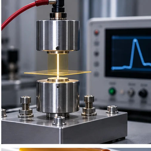
What Is Dielectric Strength?
Dielectric strength describes the electric field associated with breakdown under specified test conditions.
It is commonly reported in units such as kV/mm.
What Is Breakdown Voltage?
Breakdown voltage is the voltage at which a particular specimen fails under a defined test method.
It is commonly reported in kV.
Understanding the Basic Relationship
For a uniform electric field, the nominal relationship is:
Electric field (kV/mm) = Applied voltage (kV) ÷ Film thickness (mm)
A related expression is:
Breakdown voltage ≈ Measured dielectric strength × Specimen thickness
However, the second expression is only a simplified relationship for interpreting a particular test result.
It should not be used as a universal prediction of actual breakdown voltage across different thicknesses, grades or service conditions.
Illustrative Calculation
Suppose a laboratory test reports a dielectric strength of 150 kV/mm for a specific film specimen.
For a 0.050 mm specimen:
150 kV/mm × 0.050 mm = 7.5 kV
This is an arithmetic illustration only.
It does not mean that every 50 μm film can withstand 7.5 kV in an actual product, nor does it establish a safe continuous operating voltage.
The result cannot be transferred to another thickness or product without supporting data.
Why Dielectric Strength Is Not a Fixed Universal Number
Measured dielectric strength can change with:
- Film thickness
- Electrode geometry
- Test medium
- Voltage frequency and waveform
- Voltage rise rate
- Temperature
- Humidity
- Material defects
- Specimen preparation
- Test duration
In addition, short-term breakdown testing is not equivalent to long-term insulation endurance.
Relevant Test Standards
ASTM D149 provides methods for determining dielectric breakdown voltage and dielectric strength of solid electrical insulating materials at commercial power frequencies under specified conditions.
ASTM D2305 covers multiple test methods for polymeric films used for electrical insulation, including thickness, dielectric breakdown and other electrical and physical properties.
IEC 60243 is another important family of dielectric strength test methods.
Engineers should request the actual test method, conditions and measured results rather than comparing unqualified dielectric strength figures from different suppliers.
4. How to Determine the Required Electrical Insulation Thickness
A practical selection process should begin with the electrical and mechanical design requirements.
Step 1: Define the Electrical Stress
Identify the maximum voltage difference that may occur across the insulation.
Consider:
- Normal operating voltage
- Transient or surge conditions
- AC or DC stress
- Voltage waveform
- Fault conditions
- Required production withstand testing
Do not assume that the nominal system voltage is the only relevant design input.
Step 2: Identify the Applicable Safety and Product Requirements
The insulation design may be subject to product-specific requirements for:
- Basic insulation
- Supplementary insulation
- Reinforced insulation
- Dielectric withstand
- Creepage and clearance
- Material thermal endurance
- Environmental and mechanical reliability
These terms and requirements depend on the applicable equipment standard.
A film’s thickness alone does not establish whether an assembly qualifies as basic, supplementary or reinforced insulation.
Step 3: Compare Grade-Specific Breakdown Data
Request dielectric breakdown voltage results for the actual candidate thickness.
Where possible, obtain:
- Test standard
- Specimen thickness
- Number of specimens
- Breakdown voltage results
- Statistical information
- Temperature and humidity conditions
- Electrode configuration
- Test medium and voltage waveform
A single typical value is not a substitute for the required design validation.
Step 4: Account for Thickness Tolerance and Manufacturing Variation
A nominal 50 μm film may not measure exactly 50 μm at every point.
Engineers should review the manufacturer’s thickness tolerance and applicable measurement method.
For insulation design, the minimum actual thickness may be more relevant than the nominal value.
Additional variations can arise during lamination, adhesive coating, forming and assembly.
Step 5: Evaluate Mechanical and Environmental Stress
Consider whether the film will experience:
- Sharp edges
- Compression
- Vibration
- Abrasion
- Repeated bending
- Thermal cycling
- Moisture
- Chemical exposure
- Installation damage
A film that performs well in a laboratory breakdown test may fail prematurely if the finished assembly damages the material.
Step 6: Validate the Finished Insulation System
The final design should be evaluated using the relevant component and system tests.
A material data sheet supports preliminary selection, but it does not replace validation of the actual insulation structure.
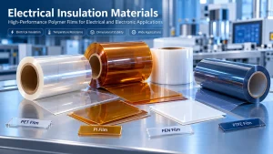
5. PET vs PI vs PPS vs PEN: Does Material Choice Change Thickness Requirements?
Yes.
Different polymers offer different combinations of dielectric properties, thermal endurance, dimensional stability, flexibility and processing behavior.
The same nominal thickness does not guarantee equivalent performance.
| Material | General Strengths | Thickness Selection Considerations | Typical Applications |
|---|---|---|---|
| PET Film | Cost-effective electrical insulation, good mechanical properties | Temperature limits, grade-specific dielectric data, flexibility | Battery liners, electrical barriers, general electronics |
| Polyimide (PI) Film | Elevated-temperature electrical insulation, thin flexible constructions | Higher-temperature exposure, bending, electrical testing | Power electronics, motors, high-temperature components |
| PPS Film | Thermal and chemical resistance, dimensional stability | Film grade, mechanical stiffness, thickness availability | Automotive electronics, inverters, industrial insulation |
| PEN Film | Dimensional stability and thermal performance for selected grades | Thermal aging, shrinkage, film construction | Electronics, electrical insulation, selected energy applications |
| PTFE Film | Chemical resistance, low friction and electrical insulation | Creep, mechanical support, thickness and processing | Specialty insulation and chemical-facing components |
PET Electrical Insulation Film
PET is often selected when cost, availability, dielectric properties and converting performance must be balanced.
It may be appropriate for battery insulation liners, electrical barriers and general electronics when the specific grade meets the design requirements.
For a detailed comparison of PET and PI, read our PI vs PET Film: Temperature, Insulation and Cost Guide.
Polyimide Electrical Insulation Film
Polyimide film is commonly evaluated where higher thermal endurance or a thin, flexible electrical insulation layer is required.
A thinner PI film may be suitable in an application where a different polymer would not meet the thermal requirements.
However, this does not mean PI can automatically replace a thicker PET film without electrical and mechanical testing.
PPS Electrical Insulation Film
PPS films may be considered in demanding electronic environments where temperature resistance, dimensional stability and chemical compatibility are important.
Thickness selection must still be based on the exact film grade and required insulation performance.
PEN Electrical Insulation Film
PEN may provide a useful alternative where dimensional stability and thermal properties are important.
For coated, laminated or adhesive-backed PEN constructions, the final insulation performance must account for all layers.
Can One Material Replace Another at a Lower Thickness?
Possibly, but only after reviewing the complete requirements.
For example, replacing a 125 μm PET film with a 50 μm PI film may change:
- Electrical withstand performance
- Mechanical protection
- Assembly stiffness
- Thermal aging behavior
- Material cost
- Adhesive compatibility
- Die-cutting performance
The replacement should be treated as an engineering design change rather than a direct thickness conversion.
6. Recommended Thickness Selection by Application
Different applications place different demands on electrical insulation films.
The following table illustrates thickness ranges that may be considered during preliminary material screening.
These ranges are not minimum safety requirements or universal recommendations.
| Application | Thicknesses to Investigate | Important Evaluation Factors |
|---|---|---|
| Thin electronic insulation layers | 12.5–50 μm | Electrical stress, flexibility, handling |
| Battery cell insulation films | 25–125 μm | Dielectric performance, abrasion, wrapping, certification |
| Battery module liners | 50–250 μm | Mechanical contact, dimensions, thermal exposure |
| Busbar insulation components | 50–250 μm | Voltage, edge geometry, thermal aging, assembly |
| Power electronics barriers | 25–125 μm | Thermal endurance, electrical stress, mounting |
| Motor or transformer film insulation | Grade-dependent | Applicable insulation system, thermal class, winding process |
| Custom die-cut insulation spacers | 50–350 μm | Shape, stiffness, compression, tolerance |
The ranges above are examples of thicknesses to investigate, not application approvals. Actual requirements may fall outside these ranges.
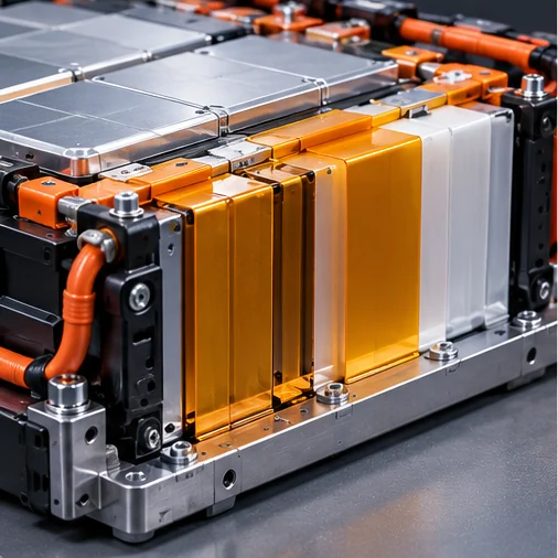
Battery Cell and Module Insulation
Battery insulation films are often selected to separate conductive components and protect against accidental electrical contact.
The required thickness depends on the cell geometry, electrical design, mechanical assembly and operating environment.
Important considerations include:
- Cell-to-cell contact
- Busbar and terminal geometry
- Abrasion during assembly
- Insulation coverage
- Thermal exposure
- Flame-retardant requirements
- Material traceability
Where a flame-retardant film is specified, verify the exact grade and recognized thickness.
For example, a UL 94 VTM-0 classification does not automatically apply to all thicknesses of a PET film family.
Likewise, a flammability classification is not proof of battery thermal runaway containment.
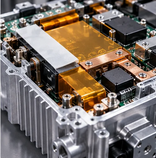
Power Electronics and Inverters
Power electronics may require thin electrical insulation barriers in compact assemblies exposed to elevated temperatures.
PI, PET, PPS or PEN may be considered depending on the thermal and electrical requirements.
A successful design must address both dielectric performance and physical assembly.
Special attention should be paid to:
- Localized hot spots
- Metal edges
- Fasteners and mounting points
- Electrical transients
- Compression and vibration
- Thermal cycling
PCB and SMT Applications
In PCB and SMT processes, insulation film thickness can affect masking, protection, assembly clearance and material handling.
However, temporary process protection and permanent electrical insulation have different qualification requirements.
A film suitable for short-term high-temperature masking should not automatically be approved as permanent electrical insulation.
Motor and Transformer Applications
Motor and transformer insulation designs may be governed by complete insulation-system requirements.
Film thickness should be evaluated together with thermal class, winding geometry, impregnation materials and relevant electrical tests.
Do not substitute a different polymer or thickness solely because its published dielectric strength appears higher.
7. Why Thicker Insulation Film Is Not Always Better
It is tempting to assume that thicker insulation automatically produces a more reliable design.
In practice, excessive thickness can introduce disadvantages.
Reduced Flexibility
Thicker films generally require more force to bend.
This can create difficulties when insulating narrow busbars, corners or complex electronic components.
Increased Assembly Thickness
Electrical equipment often has limited space.
An unnecessarily thick film can affect mechanical fit, heat transfer interfaces and fastening arrangements.
Higher Material Consumption
For the same polymer and area, increasing film thickness generally increases material volume and weight.
This can increase material costs, particularly in high-volume converting projects.
Processing Challenges
Thicker films may require different cutting tools, winding conditions or forming processes.
In some designs, thinner films are easier to process, while in others a thicker construction improves handling.
Localized Mechanical Stress
A thick film that does not conform properly to a component may develop gaps, concentrated pressure or bending stress.
Therefore, the best thickness is determined by the entire application rather than a single property.
8. Single-Layer vs Multi-Layer Electrical Insulation Films
Another important design decision is whether to use one thick film or multiple thinner layers.
Single-Layer Construction
Potential advantages include:
- Simpler material structure
- Fewer interfaces
- Easier thickness measurement
- Potentially simpler converting and assembly
However, the design must still meet all required electrical and mechanical performance criteria.
Multi-Layer Construction
Multi-layer constructions may be useful where the design requires:
- Different material properties in one component
- Adhesive bonding
- Mechanical reinforcement
- Surface protection
- Special assembly geometry
For example, a laminate may combine an electrical insulation film with an adhesive layer and release liner.
However, total laminate thickness is not necessarily equal to the effective electrical insulation thickness.
Adhesives, voids, interfaces and defects can influence the performance of the finished structure.
Does Doubling the Number of Layers Double Breakdown Voltage?
Not necessarily.
Electrical stress distribution, interlayer contact, trapped air, defects and the characteristics of each layer can change the behavior of a multi-layer insulation system.
The complete laminate should be tested rather than assuming its performance is the sum of individual film test results.
For custom constructions, explore our Precision Converting Services.
9. How Thickness Affects Slitting, Die Cutting and Finished Part Quality
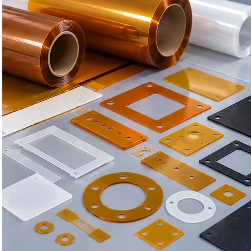
Material thickness is not only an electrical design parameter.
It also influences the way an insulation film can be converted into usable components.
Precision Slitting
For roll materials, thickness affects winding behavior, web tension and finished roll stability.
Important parameters include:
- Master roll width
- Finished slit width
- Thickness and thickness tolerance
- Roll length
- Core size
- Maximum roll diameter
- Edge quality requirements
HighTemp Material offers Precision Film Slitting Services for high-performance insulation films and other flexible materials.
Custom Die Cutting
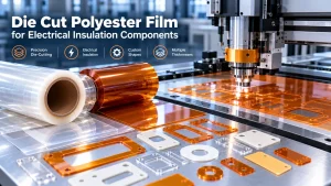
Battery and electronics manufacturers frequently require insulation films in custom shapes.
Typical examples include:
- Busbar insulation covers
- Battery module liners
- Electrical isolation washers
- Protective film spacers
- Insulation pads
- Adhesive-backed insulating components
Thickness can affect tooling selection, edge quality, dimensional consistency and the ability to cut intricate features.
Our Custom Die Cutting Services support drawing-based evaluation of PET, PI, PPS, PEN and other suitable insulation materials.
Adhesive-Backed Insulation Films
When an insulation film is supplied with adhesive, the final construction may include:
- Base insulation film
- Adhesive layer
- Release liner
- Additional protective or functional layers
The customer should specify whether the required thickness refers to the base film alone or the complete finished laminate.
This distinction is especially important for electrical insulation testing and dimensional control.
10. Electrical Insulation Film Thickness Selection Checklist
Before requesting a quotation or approving a material, confirm the following information.
| Requirement | Information to Provide |
|---|---|
| Application | Battery, busbar, inverter, PCB, motor or other equipment |
| Insulation function | Electrical barrier, mechanical protection or both |
| Voltage requirements | Normal, transient and required withstand conditions |
| Material preference | PET, PI, PPS, PEN, PTFE or alternative |
| Film thickness | Target nominal thickness and allowable tolerance |
| Electrical data | Breakdown voltage, dielectric strength and test conditions |
| Operating temperature | Continuous and peak temperatures |
| Mechanical conditions | Bending, abrasion, compression and vibration |
| Environment | Humidity, chemicals, oils and contamination |
| Flammability | Required classification and supporting documentation |
| Adhesive requirement | Non-adhesive, single-sided or double-sided |
| Finished format | Master roll, slit roll, sheet or die-cut part |
| Drawing | Dimensions, holes, cutouts and tolerances |
| Quantity | Sample requirement and annual production demand |
| Documentation | TDS, relevant certificates and customer specifications |
Recommended Engineering Review Sequence
Define the application → Identify the electrical requirements → Select candidate materials → Compare available thicknesses → Review test data → Evaluate converting feasibility → Validate the finished assembly.
This approach is more reliable than selecting a thickness based only on a supplier’s typical dielectric strength value.
11. Request Electrical Insulation Film Thickness and Material Support
HighTemp Material focuses on high-performance insulation films and custom precision-converting solutions for industrial electronics and energy-related applications.
Our relevant material and service categories include:
- PET electrical insulation films
- Polyimide (PI) insulation films
- PPS and PEN films
- Flame-retardant film options, subject to grade and certification
- Custom film slitting
- Precision die-cut insulation components
- Adhesive-backed film constructions
- Drawing-based converting evaluation
We can help review candidate materials, available thicknesses, dimensions, converting feasibility and supporting documentation based on your application.
Need Help Choosing an Insulation Film Thickness?
Please send us:
- Application and operating conditions
- Required material or current material grade
- Target thickness or available installation space
- Electrical performance requirements
- Part drawing or roll dimensions
- Estimated order quantity
- Required test reports or certificates
Our team can discuss suitable material options and sample evaluation requirements.
Contact HighTemp Material for an Insulation Film Quote
Frequently Asked Questions
What is the most common thickness for electrical insulation film?
There is no single universal thickness. Common nominal options include 25, 50, 75, 100, 125 and 250 μm, depending on the polymer grade and application. The correct thickness must be selected using electrical, mechanical and thermal requirements.
Is 25 μm PET film suitable for battery insulation?
It may be suitable for certain battery insulation applications if the exact film grade and finished assembly meet the required electrical, thermal, mechanical and documentation requirements. Thickness alone does not establish suitability.
Is thicker insulation film always better?
No. Greater thickness may provide additional physical separation, but it can also reduce flexibility, increase cost and create assembly challenges. The correct thickness balances electrical performance with mechanical and manufacturing requirements.
How does dielectric strength relate to insulation film thickness?
Dielectric strength is an electric field value measured under specified test conditions. Breakdown voltage is related to specimen thickness, but the relationship is not universally linear across different film thicknesses and materials.
Can a thinner polyimide film replace a thicker PET film?
Potentially, but only after evaluating the specific grades and validating electrical, mechanical and thermal performance. PI and PET should not be substituted using thickness alone.
What is the difference between nominal thickness and minimum thickness?
Nominal thickness is the stated product thickness. Minimum thickness is the lowest thickness permitted by the applicable tolerance or specification. Both may be important when evaluating insulation performance.
Does adhesive thickness count as electrical insulation thickness?
It depends on the design and the qualification of the complete adhesive laminate. Adhesive thickness should not automatically be treated as equivalent to the dielectric performance of the base insulation film.
Can electrical insulation films be custom die-cut?
Yes. Suitable PET, PI, PPS, PEN and other insulation films can be slit or die-cut into application-specific components, subject to material properties, dimensions, tolerances and processing feasibility.
Conclusion
Choosing the right electrical insulation film thickness requires a combination of electrical design, material science and manufacturing evaluation.
Thickness influences electric field, mechanical durability, flexibility, assembly fit and cost, but it does not independently determine whether an insulation system is safe.
PET, PI, PPS and PEN films offer different property combinations, and the most appropriate material should be selected using grade-specific test data and actual application requirements.
For battery packs, busbars, power electronics and industrial electrical assemblies, engineers should evaluate the complete insulation system rather than relying on a single dielectric strength figure.
HighTemp Material supports electrical insulation film sourcing discussions and precision converting projects involving custom thicknesses, slit rolls and die-cut components.
Request Material and Thickness Selection Support
Technical References
- ASTM D149 — Dielectric Breakdown Voltage and Dielectric Strength of Solid Electrical Insulating Materials
- ASTM D2305 — Standard Test Methods for Polymeric Films Used for Electrical Insulation
- HighTemp Material — PI vs PET Film: Temperature, Insulation and Cost Comparison
Engineering disclaimer: Thickness ranges, calculations and application examples in this article are intended for preliminary material selection. They are not design approvals, certified minimum thickness requirements or substitutes for testing under applicable product standards. Final material selection must be validated using the actual grade, operating conditions and finished assembly.