
Comparing Mica, Aerogel, Ceramic Fiber, Fiberglass Composites and Intumescent Materials for Battery Thermal Propagation Protection
Lithium-ion battery packs contain large amounts of stored energy within compact assemblies. Under abnormal conditions, a battery cell may enter thermal runaway, releasing heat, gases and potentially flames or hot particles.
One of the most important challenges in battery safety engineering is limiting the effects of a failing cell on neighboring cells, modules and surrounding structures.
Thermal runaway barrier materials can form part of this protection strategy.
Mica-based sheets, aerogel insulation, ceramic fiber materials, fiberglass composites and intumescent systems are among the material families considered for different thermal protection functions.
However, these materials are not interchangeable.
A material with low thermal conductivity may not provide adequate resistance to hot-particle impact. A material that withstands high temperatures may transmit too much heat through a thin section. A flame-retardant polymer film may provide useful electrical insulation but may not survive direct exposure to severe thermal runaway conditions.
The correct thermal barrier is not simply the material with the highest published temperature rating. It is the construction that satisfies the required thermal, mechanical, electrical and installation performance under representative battery failure conditions.
This guide explains the main barrier material families, design considerations, qualification methods and procurement requirements for EV and energy storage battery applications.
1. Understanding Thermal Runaway in Lithium-Ion Battery Packs
Thermal runaway is a self-accelerating process in which heat generation within a battery cell becomes difficult to control.
Depending on the cell chemistry, state of charge, design and initiating event, thermal runaway may involve rapid temperature rise, venting, gas release, fire and mechanical effects.
Potential initiating conditions include internal defects, electrical abuse, external heating or mechanical damage.
The behavior of a failing cell varies significantly by cell format, chemistry and construction.
Thermal Runaway vs Thermal Propagation
These terms describe different concerns.
Thermal runaway occurs within an individual cell.
Thermal propagation occurs when the effects of a failing cell cause additional cells or parts of the battery system to experience damaging thermal conditions or enter runaway themselves.
Thermal barrier materials are generally evaluated for their contribution to limiting heat transfer and protecting neighboring components.
They do not eliminate the need for cell-level safety, battery management systems, venting strategies and appropriate pack architecture.
Why Material Selection Is Difficult
During an abnormal battery event, a barrier may encounter several stresses simultaneously:
- High heat flux
- Elevated surface temperatures
- Hot gases
- Flames
- Ejected particles
- Pressure and mechanical loading
- Changes in adjacent component geometry
A laboratory temperature rating cannot fully describe these combined conditions.
2. How Thermal Runaway Barriers Work
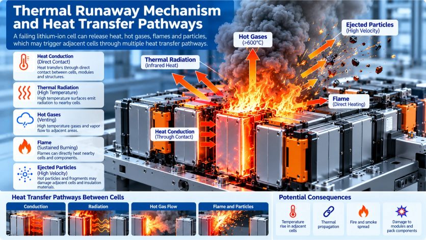
Thermal runaway barriers are intended to reduce the transfer of damaging thermal energy or provide separation between components.
The actual protective function depends on the design.
Heat Conduction
Heat can transfer through direct contact between cells, structural parts and barrier materials.
A low thermal conductivity material may reduce conductive heat transfer, but its performance depends on thickness, contact pressure, temperature and the complete assembly.
Thermal Radiation
A failing cell or hot surface can transfer energy through thermal radiation.
Surface properties, geometry and shielding influence radiative heat transfer.
Hot Gas and Flame Exposure
Battery venting can expose adjacent materials to hot gases and, in some events, flames.
The barrier must be assessed for the actual exposure path and duration.
Ejected Particles
Hot particles and fragments may damage thin or mechanically fragile materials.
Resistance to puncture, erosion and mechanical disruption can be important.
Maintaining Barrier Integrity
A barrier that initially reduces heat transfer may lose effectiveness if it cracks, moves, delaminates or develops gaps.
Thermal performance and structural integrity must therefore be considered together.
3. Where Thermal Runaway Barrier Materials Are Used
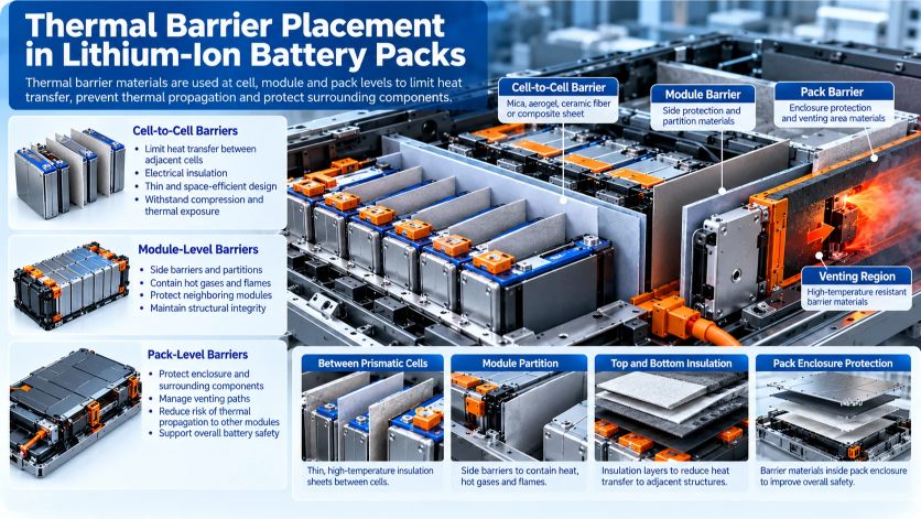
Barrier placement is determined by the battery architecture and safety objectives.
Cell-to-Cell Barriers
Materials positioned between adjacent cells may help limit heat transfer.
For densely packed cells, available thickness and compression requirements can be important.
Potential considerations include:
- Thermal resistance
- Electrical insulation
- Compression behavior
- Mechanical durability
- Dimensional stability
- Installation tolerance
Module-Level Barriers
Module-level protection may include side barriers, partitions and protective layers.
These components may need to accommodate larger geometries and structural interfaces.
Pack-Level Barriers
Pack-level barriers may protect enclosure regions, neighboring modules or other components from thermal exposure.
Some designs require barriers around specific venting or heat-release paths.
Barriers Near Electrical Components
Thermal protection materials may be installed near busbars, terminals and electrical connections.
If electrical insulation is required, the complete barrier construction must also meet the applicable dielectric and insulation requirements.
Battery Architecture Matters
Cylindrical, prismatic and pouch-cell systems can have different venting behavior, mechanical constraints and propagation pathways.
A barrier solution suitable for one architecture should not be transferred to another without appropriate validation.
4. Key Performance Requirements for Thermal Runaway Barrier Materials
A complete material specification should address more than maximum temperature.
Thermal Resistance Under Relevant Exposure
Determine the thermal conditions the barrier must withstand.
Important variables include exposure temperature, heat flux, duration and heating rate.
Thermal Conductivity
Thermal conductivity describes heat conduction through a material.
However, room-temperature thermal conductivity alone may not predict performance under severe thermal exposure.
The material’s conductivity and structure may change with temperature.
Backside Temperature
A useful system-level question is how much the barrier limits the temperature rise on its protected side.
Backside temperature depends on:
- Material construction
- Thickness
- Exposure conditions
- Contact geometry
- Heat capacity
- Mechanical compression
- Test duration
Mechanical Integrity
Evaluate whether the material can retain its protective function after vibration, handling, compression or thermal exposure.
Electrical Insulation
Where required, review dielectric strength, insulation resistance and the behavior of the complete construction.
Thickness and Weight
Battery packaging places constraints on space and mass.
A thicker barrier may improve certain thermal outcomes but can reduce packaging efficiency.
Environmental Durability
Humidity, chemicals, aging and mechanical movement may affect the material or its interfaces.
Manufacturing Compatibility
Consider die-cutting, lamination, installation, dust generation, edge protection and quality consistency.
5. Comparison of Common Thermal Runaway Barrier Materials
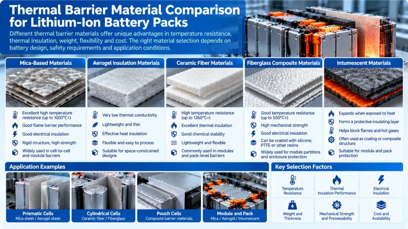
Several material families are used or evaluated in battery thermal protection systems.
The table below describes potential characteristics, not verified performance rankings.
| Material Family | Potential Advantages | Important Limitations | Selection Questions |
|---|---|---|---|
| Mica-based sheets | High-temperature electrical and thermal barrier potential | Brittleness, binder behavior, handling | What is the exact mica construction and tested exposure? |
| Aerogel composites | Low thermal conductivity in suitable grades | Compression, dust, cost, high-temperature structural changes | How does the composite perform under actual heat flux and compression? |
| Ceramic fiber materials | High-temperature insulation potential | Fiber handling, mechanical integrity, environmental and occupational considerations | Is the exact fiber chemistry and construction appropriate? |
| Fiberglass composites | Reinforcement and structural flexibility | Glass composition, binder and coating limitations | Does the complete composite retain integrity during exposure? |
| Intumescent materials | Expansion can create a protective char or barrier | Activation conditions, expansion space, char strength | Is expansion effective in the installed geometry? |
| High-temperature polymer films | Thin electrical insulation and protective layers | Severe thermal exposure may exceed film capability | Is the film an auxiliary layer or a validated primary barrier? |
5.1 Mica-Based Barrier Materials
Mica-based sheets and laminates are considered for applications requiring electrical insulation and elevated-temperature resistance.
Their performance depends on the mica type, binder, reinforcement and manufacturing process.
Potential advantages include:
- Electrical insulation in suitable constructions
- Elevated-temperature stability
- Availability in sheet or converted-part formats
Important considerations include brittleness, cracking, edge damage and the behavior of binders or supporting layers.
A mica-based product should not be described as a qualified thermal runaway barrier solely because it contains mica.
5.2 Aerogel-Based Insulation
Aerogel materials are known for low thermal conductivity, and certain reinforced aerogel composites may be considered for battery thermal barriers.
Potential advantages include thin-profile thermal insulation and lightweight construction.
However, engineers should verify:
- Thermal performance at relevant temperatures
- Compression response
- Mechanical durability
- Handling and particulate behavior
- Performance after environmental aging
An aerogel material’s room-temperature conductivity does not establish its performance during thermal runaway exposure.
5.3 Ceramic Fiber Materials
Certain ceramic fiber materials can provide insulation at elevated temperatures.
Their suitability depends on fiber composition, density, binder, reinforcement and construction.
Mechanical integrity and handling requirements may be significant.
Occupational health and environmental considerations should also be reviewed for the specific fiber type and applicable jurisdiction.
5.4 Fiberglass Composites
Fiberglass can provide mechanical reinforcement in composite barrier systems.
However, the performance of a fiberglass composite depends on its coating, binder, resin or other constituents.
The presence of glass fiber alone does not guarantee that the complete material will maintain integrity under severe thermal exposure.
5.5 Intumescent Materials
Intumescent materials are designed to expand or form a protective structure when exposed to particular thermal conditions.
Their effectiveness depends on:
- Activation temperature
- Expansion ratio
- Available expansion space
- Char strength
- Adhesion and retention
- Exposure duration
Intumescent performance must be tested in the actual installation geometry.
5.6 High-Temperature Polymer Films
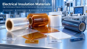
PI, PET, PEN and PTFE films can serve useful functions in battery assemblies, including electrical insulation and selected protective layers.
However, conventional thin polymer films should not be assumed to provide sufficient primary protection against direct thermal runaway exposure.
They may be used as auxiliary electrical insulation layers or as part of a validated multilayer construction.
For additional guidance, read our EV Battery Insulation Materials Selection Guide and Battery Insulation vs Thermal Management.
6. Why Multilayer Barrier Constructions May Be Necessary
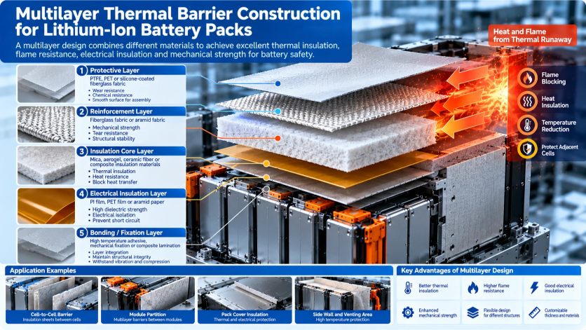
A single material does not always provide the desired combination of thermal insulation, electrical performance, flexibility and mechanical durability.
A multilayer design may combine different functions.
For example, a hypothetical barrier could contain:
- A protective facing layer
- A mechanically reinforced layer
- A thermal insulation core
- An electrical insulation layer
- A mechanical fixing or bonding system
This is a conceptual construction, not a recommended universal stack-up.
Benefits of Functional Separation
Different layers can be selected for different requirements.
A thermal core may reduce heat transfer, while a reinforcement layer helps maintain handling integrity.
An electrical insulation layer may provide a defined dielectric function.
Interface Risks
Adding layers also introduces potential failure points.
These may include:
- Delamination
- Adhesive degradation
- Differential thermal expansion
- Moisture ingress
- Edge exposure
- Loss of structural retention
Therefore, multilayer systems must be evaluated as complete constructions.
7. Design Considerations for Thermal Barrier Components
Material selection and part design should be developed together.
Thickness
Thickness influences heat transfer, packaging space and mechanical behavior.
The required thickness should be established using relevant thermal and system testing rather than a generic rule.
Edge Coverage
Unprotected edges and gaps can create unintended thermal pathways.
Coverage requirements should account for tolerances and movement.
Compression and Contact Pressure
Some materials change thickness or thermal behavior under compression.
For cell-to-cell barriers, evaluate the actual installed pressure range.
Die-Cut Geometry
Holes, slots and internal corners may affect both thermal coverage and mechanical strength.
Designs should avoid unnecessary stress concentrations.
Fixing and Adhesive Systems
Adhesive systems can simplify installation, but they may become limiting components during thermal exposure.
Where necessary, mechanical retention may be considered.
Assembly Tolerances
Part dimensions, stack tolerances and positioning accuracy influence whether the barrier remains correctly installed.
Cleanliness and Handling
Certain insulation materials may generate dust or require special handling.
Manufacturing cleanliness requirements should be specified early.
For design guidance on precision-converted insulation components, see our Die-Cut Insulation Parts Design Guide.
8. Common Thermal Barrier Failure Modes
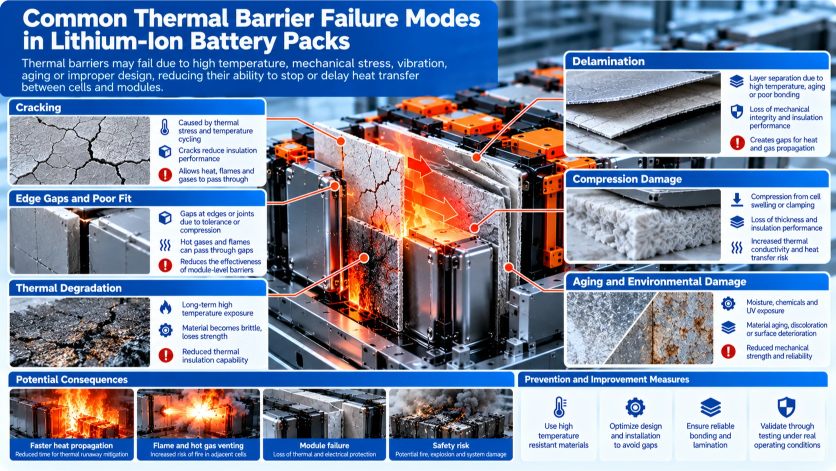
Cracking and Mechanical Fracture
Brittle or insufficiently supported materials may crack during assembly or vibration.
Edge Gaps
Poor dimensional control or installation can leave exposed pathways.
Delamination
Multilayer constructions may separate under thermal or mechanical stress.
Compression Damage
Some low-density insulation materials may lose thickness or change structure under compression.
Hot Gas Bypass
A barrier may perform adequately in a flat thermal test but fail to protect an assembly if hot gases can travel around it.
Loss of Integrity During Exposure
Binders, adhesives, coatings or reinforcements may deteriorate before the main insulating phase.
Incorrect Material Substitution
Replacing a qualified material with another material of similar appearance or nominal temperature rating can introduce unexpected risks.
A thermal barrier failure should be investigated at the material, component and system levels.
9. Testing and Qualification of Thermal Runaway Barrier Materials
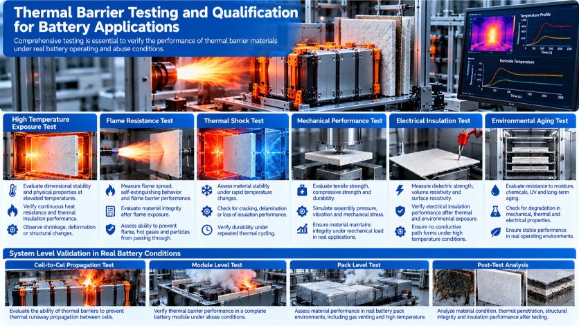
There is no single material property that establishes thermal runaway protection.
A qualification program should be defined according to the intended function.
Thermal Exposure Testing
Evaluate the material under representative temperature, heat flux and duration conditions.
Measure changes in structure and protective performance.
Backside Temperature Testing
Where appropriate, measure the temperature on the protected side under a defined thermal exposure.
Flame and Hot Gas Exposure
Assess the barrier against relevant flame or hot gas conditions when these are part of the design requirements.
Mechanical Testing
Depending on the construction, evaluate:
- Tensile or flexural properties
- Compression
- Puncture resistance
- Vibration durability
- Handling damage
Electrical Testing
Where the barrier also serves an electrical insulation function, relevant tests may include dielectric withstand and insulation resistance.
Environmental Aging
Humidity, temperature cycling and chemical exposure may affect performance over time.
Component and Pack-Level Testing
Material-level testing should be followed by representative assembly evaluation.
Battery-system thermal propagation performance depends on many factors beyond the barrier material.
Relevant regulatory or technical references may include:
- UNECE Regulation No. 100, where applicable
- UL 2580 for relevant EV battery applications
- UL 9540A for evaluating thermal runaway fire propagation characteristics in battery energy storage systems, where applicable
- IEC 62619 for relevant industrial lithium battery safety requirements
These documents have different scopes and should not be treated as interchangeable material certifications.
Confirm the current edition, applicability and required acceptance criteria for the target market and product.
10. Common Material Selection Mistakes
Mistake 1: Choosing by Maximum Temperature Rating
A maximum temperature rating does not describe heat-flux performance, structural integrity or thermal propagation resistance.
Better approach: Define the actual exposure conditions.
Mistake 2: Selecting Only by Thermal Conductivity
Low thermal conductivity is useful but insufficient on its own.
Better approach: Evaluate the complete thermal and mechanical behavior.
Mistake 3: Treating UL 94 as Proof of Thermal Runaway Protection
A flammability classification does not establish battery thermal propagation performance.
Better approach: Use application-relevant barrier and system testing.
Mistake 4: Ignoring Gas and Particle Exposure
A barrier designed only for conductive heat transfer may not address hot gases or particles.
Better approach: Review all relevant exposure mechanisms.
Mistake 5: Ignoring Mechanical Installation
A material that cracks or shifts during assembly may not provide the intended coverage.
Better approach: Validate the installed geometry and retention method.
Mistake 6: Assuming a Polymer Film Can Replace a Dedicated Thermal Barrier
A thin electrical insulation film may not withstand direct thermal runaway exposure.
Better approach: Separate electrical insulation and thermal event protection requirements.
11. Engineering Selection Workflow
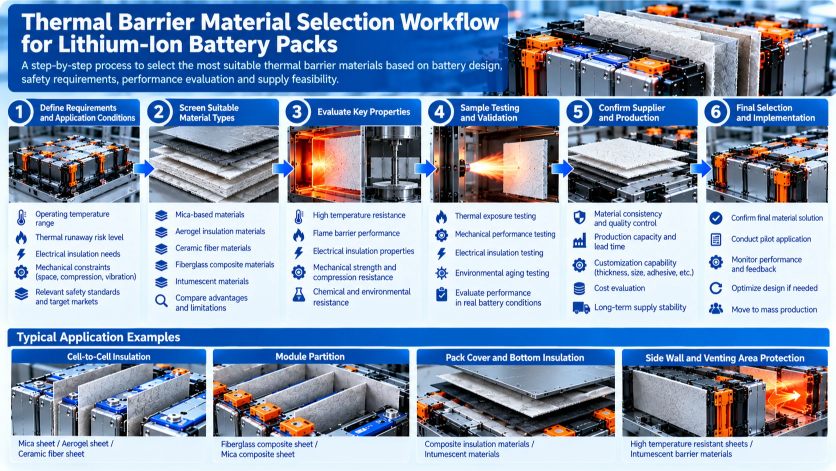
Step 1: Define the Battery Architecture
Identify cell format, chemistry, module configuration and barrier location.
Step 2: Define the Protection Objective
Determine whether the component must reduce conductive heat transfer, resist flame exposure, maintain electrical insulation or perform multiple functions.
Step 3: Establish Exposure Conditions
Specify relevant temperature, heat flux, duration, gas exposure and mechanical conditions.
Step 4: Shortlist Material Families
Compare mica, aerogel, ceramic fiber, fiberglass composites, intumescent systems and suitable multilayer constructions.
Step 5: Review Installation Constraints
Consider thickness, weight, compression, dimensions, handling and retention.
Step 6: Prototype and Test
Evaluate representative barrier parts and complete assemblies.
Step 7: Confirm Documentation and Supply
Review grade identification, specifications, available test reports, traceability and manufacturing requirements.
Step 8: Qualify Before Production
Do not substitute material families or constructions without appropriate engineering review and validation.
12. RFQ Checklist for Thermal Runaway Barrier Materials
For effective technical communication, provide the following information.
| RFQ Item | Information Required |
|---|---|
| Application | EV battery, ESS, module or pack |
| Cell format | Cylindrical, prismatic or pouch |
| Barrier location | Cell-to-cell, module, pack or venting region |
| Protection objective | Thermal insulation, flame resistance, electrical insulation or combined |
| Exposure requirements | Temperature, heat flux, duration and test conditions |
| Material preference | Mica, aerogel, ceramic fiber, composite or open |
| Thickness | Nominal thickness and tolerance |
| Mechanical requirements | Compression, flexibility, puncture or vibration |
| Electrical requirements | Dielectric withstand or insulation resistance |
| Dimensions | Drawing, holes, cutouts and edge details |
| Fixing method | Adhesive, mechanical retention or other |
| Documentation | TDS, test reports and required compliance evidence |
| Quantity | Samples, prototypes and annual demand |
Where a specific material property or certification is mandatory, request the corresponding grade-specific documentation.
13. Thermal Barrier and Electrical Insulation Material Sourcing
HighTemp Material works with industrial customers sourcing high-temperature films, electrical insulation materials and precision-converted components.
For battery-related projects, we can discuss requirements involving:
- Electrical insulation films
- High-temperature polymer films
- Selected insulating sheet materials
- Custom-cut insulation components
- Precision slitting and converting
Potential material availability, grade-specific thermal barrier performance, testing documentation and manufacturing feasibility must be confirmed before quotation or qualification.
Our relevant converting pages include:
Request Material Selection Support
Are you developing an electrical insulation component or evaluating a thermal barrier construction for a lithium-ion battery system?
Send us your application, material requirements, drawings, thickness, relevant test criteria and expected quantity.
Contact HighTemp Material to discuss available materials and converting options.
Frequently Asked Questions
What materials are commonly considered for battery thermal runaway barriers?
Material families may include mica-based sheets, aerogel composites, ceramic fiber materials, fiberglass composites and intumescent systems. Their suitability depends on the exact construction and application requirements.
Is mica suitable for thermal runaway protection?
Certain mica-based constructions may be suitable for specific thermal barrier functions. However, performance must be verified under representative exposure and assembly conditions.
Is aerogel better than mica for battery insulation?
Neither is universally better. Aerogel composites and mica-based materials have different thermal, mechanical and processing characteristics. The selection depends on the complete application.
Can polyimide film stop thermal runaway propagation?
Conventional thin PI film should not be assumed to provide adequate primary protection against severe thermal runaway exposure. It may serve as electrical insulation or an auxiliary layer in a validated construction.
What is the difference between flame retardancy and thermal runaway resistance?
Flame retardancy describes behavior under a defined flammability test. Thermal runaway resistance concerns performance under abnormal battery events involving heat, gases and potentially flames or particles.
How is thermal barrier thickness selected?
Thickness should be selected through thermal analysis, packaging assessment and representative testing. A universal thickness recommendation is not appropriate.
Does low thermal conductivity guarantee good thermal runaway protection?
No. High-temperature stability, mechanical integrity, gas exposure and installation geometry can also determine performance.
Can thermal barrier materials provide electrical insulation?
Some materials can provide both functions, but electrical properties must be verified for the exact construction and application.
Which standards apply to battery thermal runaway testing?
Applicable standards depend on the battery type, market and intended qualification. Examples may include UL 2580, UL 9540A and relevant vehicle or industrial battery standards. Their scopes differ.
What should be included in a thermal barrier material RFQ?
Include the battery architecture, barrier location, thermal exposure, electrical and mechanical requirements, thickness, drawing, qualification criteria and estimated quantity.
Conclusion
Thermal runaway barrier materials are important elements of lithium-ion battery safety engineering, but their effectiveness depends on more than a material name or temperature rating.
Mica, aerogel, ceramic fiber, fiberglass composites and intumescent materials provide different potential advantages and limitations.
A reliable selection process must consider heat transfer, hot gas exposure, mechanical integrity, electrical insulation, thickness, installation geometry and representative testing.
The best solution is the barrier construction that meets the defined protection objective within the actual battery system.
Contact HighTemp Material for electrical insulation material and custom converting discussions.
Engineering disclaimer: This guide provides general material-selection information. It does not claim that any particular material supplied by HighTemp Material has passed thermal runaway, thermal propagation, flame resistance or battery safety testing. All material properties, certifications, supplier capabilities and qualification requirements must be verified for the exact grade and application.