
How to Select Electrical Insulation Films, Laminates and Custom Die-Cut Components for High-Voltage Electric Vehicle Power Systems
Electric vehicle powertrains depend on electrical insulation systems that operate under demanding combinations of voltage, temperature, vibration, moisture and mechanical stress.
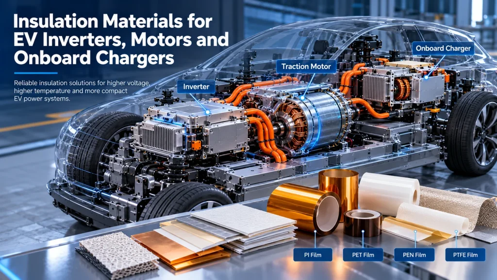
Three major components illustrate the challenges particularly well: the traction inverter, the electric motor and the onboard charger (OBC).
Although these systems all require reliable electrical insulation, their operating environments are different.
An inverter may expose insulation to fast-switching voltage waveforms and localized heat. A traction motor combines electrical stress with winding temperatures, vibration and contact with impregnation materials or cooling fluids. An onboard charger introduces additional considerations involving high-frequency magnetic components, PCB isolation and compact packaging.
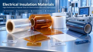
Polyimide (PI), polyester (PET), polyethylene naphthalate (PEN), polytetrafluoroethylene (PTFE) and composite insulation materials can all play roles in these applications.
However, choosing the right material requires more than comparing dielectric strength or maximum temperature ratings.
The correct insulation solution must satisfy electrical, thermal, mechanical and manufacturing requirements in the actual installed construction.
This guide explains where insulation is used in EV power electronics, how different material families compare, which failure mechanisms deserve attention and what engineers should verify before approving a material for production.
1. Why Electrical Insulation Matters in EV Power Systems
EV traction inverters, motors and onboard chargers convert, transfer or control electrical energy.
Their insulation systems help maintain separation between conductive components and prevent unintended electrical paths.
Depending on the component, insulation may provide:
- Separation between energized conductors and grounded structures
- Insulation between winding turns, phases or layers
- Electrical barriers around busbars and terminals
- Protection against abrasion and mechanical damage
- Isolation between PCB circuits
- Protection against contamination and environmental exposure
- Dimensional separation in compact assemblies
The required insulation performance depends on the complete electrical system.
Relevant factors include operating voltage, switching characteristics, transient overvoltages, environmental conditions, mechanical loading and expected service life.
Material Properties Are Not the Same as System Performance
A polymer film may have a favorable dielectric strength value under laboratory conditions.
That value does not automatically establish the voltage rating of a busbar assembly, motor winding or onboard charger.
Real insulation performance depends on geometry, interfaces, thickness, edge quality, contamination, installation and the relevant qualification requirements.
Engineers should distinguish between material screening and validation of the finished insulation system.
2. Different Insulation Challenges in Inverters, Motors and Onboard Chargers
Although the three applications share certain material requirements, their insulation designs are not interchangeable.
| Application | Typical Insulation Locations | Important Engineering Challenges |
|---|---|---|
| Traction inverter | Busbars, power modules, terminal barriers, internal liners | Fast voltage transitions, high electrical stress, thermal cycling, compact geometry |
| Traction motor | Stator slots, phase separators, winding layers, lead insulation | Winding temperature, vibration, abrasion, partial discharge, impregnation compatibility |
| Onboard charger | Transformers, inductors, PCB barriers, insulating sheets | High-frequency operation, primary-secondary isolation, temperature, creepage and clearance |
Fast-Switching Power Electronics
Modern power converters may use silicon or wide-bandgap semiconductor devices.
Fast switching can introduce steep voltage transitions, ringing and repetitive electrical stress.
These conditions can affect insulation requirements, particularly at vulnerable interfaces or in systems where partial discharge is relevant.
High-Temperature Exposure
Insulation components may experience heat generated by copper losses, semiconductor devices, magnetic components and nearby structures.
Continuous operating temperatures and short-duration thermal excursions should be evaluated separately.
Mechanical and Environmental Exposure
Vibration, expansion, cooling-fluid contact, moisture and contamination may degrade insulation over time.
A material that performs well in a flat laboratory specimen may behave differently after installation around edges, slots or complex geometries.
3. Insulation Materials for EV Traction Inverters
Traction inverters convert battery DC power into controlled electrical output for the traction motor.
Their insulation systems must accommodate compact electrical layouts, switching stresses and local heat generation.
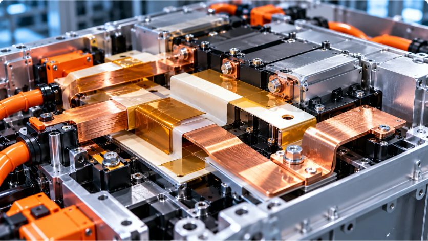
Busbar Insulation
Busbars are used to distribute electrical power within inverter assemblies.
Potential insulation solutions include:
- Polymer film barriers
- Adhesive-backed insulating films
- Custom die-cut insulating sheets
- Formed or laminated insulation components
- Coated or encapsulated busbar constructions
Material selection should consider operating voltage, edge geometry, thermal exposure and mechanical retention.
Power Module Insulation
Power modules involve multiple electrical and thermal interfaces.
Some electrical isolation functions are provided by engineered ceramic substrates or other specialized package components rather than ordinary polymer films.
Polymer insulation may still be relevant for auxiliary barriers, covers and nearby conductive features.
Engineers should not assume that a polymer sheet can replace a designed power-module isolation substrate.
Fast-Switching Voltage Stress
Inverter insulation may be exposed to repetitive pulses and high rates of voltage change.
Relevant considerations include:
- Voltage waveform
- Repetitive peak voltage
- Switching frequency
- Transient overshoot
- Partial discharge behavior where applicable
- Environmental conditions
A conventional dielectric breakdown test alone may not represent these stresses.
Design Considerations
For custom inverter insulation parts, review:
- Coverage around conductive edges
- Hole and slot positions
- Minimum bend geometry
- Thickness and dimensional tolerances
- Adhesive compatibility
- Assembly method
- Thermal expansion mismatch
Engineering recommendation: Qualify the insulation in a representative inverter assembly, particularly when fast-switching voltage stress and complex busbar geometry are involved.
4. Insulation Materials for EV Traction Motors
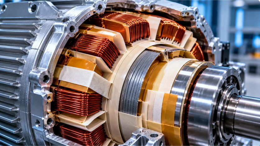
Traction motors place distinctive demands on electrical insulation.
Motor insulation is generally an integrated system involving conductors, slot liners, phase separators, winding insulation, impregnation materials and other components.
Slot Insulation
Slot liners separate windings from the stator core.
Suitable constructions must withstand installation stresses and remain effective during motor operation.
Relevant properties may include:
- Dielectric performance
- Tear and puncture resistance
- Flexibility
- Thermal endurance
- Abrasion resistance
- Dimensional stability
Phase Insulation
Phase separators help maintain electrical separation between different winding phases.
Their geometry and mechanical durability are important during winding insertion and long-term operation.
Turn and Layer Insulation
Insulation between winding turns or layers is influenced by the winding construction.
The complete insulation system may involve magnet-wire enamel, tapes, films and impregnation materials.
Polymer Films and Composite Laminates
PI, PET, PEN and certain composite materials may be considered for specific motor insulation functions.
However, motor applications often require specialized insulation systems with validated thermal endurance and compatibility.
For example, composite slot insulation materials may combine films with fibrous layers to balance mechanical handling and electrical performance.
The actual construction must be evaluated rather than relying only on the properties of the central film.
Inverter-Fed Motor Stress
Motors supplied by PWM inverters can experience voltage transients and non-sinusoidal electrical stresses.
Winding design, cable length, rise time and insulation construction can influence the resulting stress.
Partial discharge behavior may be relevant depending on the motor voltage class and insulation design.
Motor Qualification
A film’s generic temperature rating does not establish the thermal class of a complete motor insulation system.
System-level thermal endurance and electrical qualification may be required.
Engineering recommendation: Specify the entire winding insulation construction and assess compatibility with the impregnation process, cooling environment and expected electrical waveform.
5. Insulation Materials for Onboard Chargers
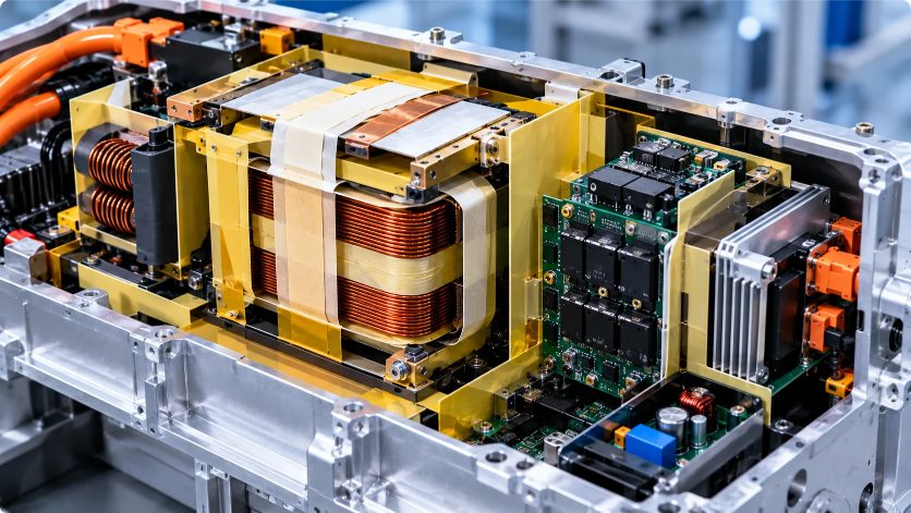
An onboard charger converts external AC power into DC power for charging the traction battery.
Its insulation system must address both electrical safety and power-conversion performance.
High-Frequency Transformers
High-frequency transformers may require insulation between winding layers and between primary and secondary circuits.
Potential material forms include:
- Thin insulation films
- Electrical insulation tapes
- Layer separators
- Bobbin insulation components
- Engineered multilayer constructions
Selection depends on the transformer design and applicable safety requirements.
Inductors and Magnetic Components
Magnetic components may use films, tapes or formed insulation pieces to separate conductors from cores or adjacent structures.
Temperature exposure, winding pressure and processing compatibility are important.
PCB Insulation
Onboard charger PCBs may require insulating barriers around selected components or high-voltage regions.
Insulating sheets can complement the PCB design but do not replace appropriate creepage, clearance and insulation coordination.
Primary-Secondary Isolation
Safety isolation between circuits must be established according to the applicable product standard and insulation coordination requirements.
A material datasheet cannot independently establish whether a finished transformer or charger provides basic, supplementary or reinforced insulation.
High-Frequency Material Considerations
Depending on the application, relevant electrical properties may include:
- Dielectric strength
- Dielectric constant
- Dissipation factor
- Volume resistivity
- Partial discharge behavior
- Thermal endurance
For high-frequency applications, dielectric losses and field distribution may be relevant, but their significance depends on the actual design.
Engineering recommendation: Evaluate the complete transformer or charger construction, including winding geometry, insulation layers, spacing and manufacturing process.
6. Comparing PI, PET, PEN, PTFE and Composite Insulation Materials
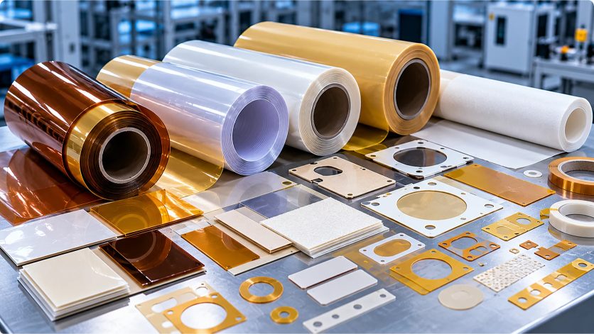
No single polymer film is suitable for every EV inverter, motor or onboard charger application.
The following comparison is intended for initial material screening.
| Material | Potential Advantages | Selection Limitations | Applications to Evaluate |
|---|---|---|---|
| PI film | Elevated-temperature insulation potential; flexible thin-film formats | Grade-specific thermal and electrical behavior; cost | Inverter barriers, motor insulation components, transformer insulation |
| PET film | Cost-effective converting options; widely used electrical insulation family | Temperature limits, shrinkage, grade-specific flame behavior | Liners, insulating sheets, selected motor and OBC components |
| PEN film | Potential thermal and dimensional advantages over certain PET grades | Grade availability and qualification requirements | Precision electrical insulation, selected motor and converter applications |
| PTFE film | Chemical resistance, low-friction surface and specialized electrical properties | Creep, dimensional behavior, bonding difficulty | Specialized high-frequency or chemically demanding insulation |
| Composite laminates | Ability to combine mechanical and electrical functions | Layer interfaces, binder behavior, qualification complexity | Motor slot insulation, transformer barriers, formed components |
Polyimide (PI) Film
PI films are frequently considered where elevated-temperature electrical insulation is required.
They may offer useful flexibility and electrical properties in thin sections.
However, not all PI films have the same thermal endurance, dielectric behavior or dimensional stability.
The exact grade and thickness must be verified.
Polyester (PET) Film
PET can be an economical solution for insulation components that operate within its validated thermal and electrical limits.
It is well suited to many precision converting processes.
Where flame performance is required, standard PET must not be assumed to meet a particular classification.
Polyethylene Naphthalate (PEN) Film
PEN may be considered where a selected grade provides useful thermal or dimensional properties.
Its advantages should be established through grade-specific comparison rather than generalized claims.
Polytetrafluoroethylene (PTFE) Film
PTFE offers chemical resistance and distinctive surface and dielectric characteristics.
Potential challenges include creep, dimensional change and bonding.
The suitability of PTFE depends on the mechanical and electrical construction.
Composite Insulation Systems
Composite materials can combine polymer films with fibrous layers, coatings or reinforcement.
They may be useful where handling, impregnation compatibility or mechanical durability requires more than a single film layer.
However, the performance of the complete laminate must be qualified.
Why the Exact Grade Matters
Even within the same polymer family, performance may differ because of:
- Film formulation
- Manufacturing process
- Thickness
- Orientation
- Surface treatment
- Reinforcement
- Adhesive construction
- Environmental conditioning
For additional background, read our PI vs PET Film Comparison.
7. Critical Electrical, Thermal and Mechanical Selection Properties
Dielectric Strength
Dielectric strength describes breakdown behavior under defined test conditions.
It should not be used as a direct substitute for system insulation coordination.
Partial Discharge Resistance
Partial discharge can be important in insulation systems exposed to repetitive high-voltage stress.
Where applicable, evaluate inception behavior, erosion resistance and long-term performance using appropriate test methods.
Thermal Endurance
Thermal endurance concerns the ability of an insulation material or system to maintain required properties over time at temperature.
A short-term temperature excursion is not equivalent to continuous service.
Thermal Cycling
Repeated temperature changes may contribute to stress at interfaces and dimensional movement.
The installed construction should be assessed for cracking, lifting, shrinkage and loss of coverage.
Mechanical Durability
Relevant properties may include:
- Puncture resistance
- Tear strength
- Flexibility
- Abrasion resistance
- Compression behavior
- Dimensional stability
Chemical and Process Compatibility
Motor impregnation materials, cooling fluids, cleaning chemicals and adhesives can affect insulation performance.
Compatibility must be assessed for the actual combination.
Dielectric Constant and Dissipation Factor
These properties can be important in selected high-frequency applications.
They should be measured or obtained under conditions relevant to the operating frequency and temperature.
8. Common Insulation Failure Modes and Prevention
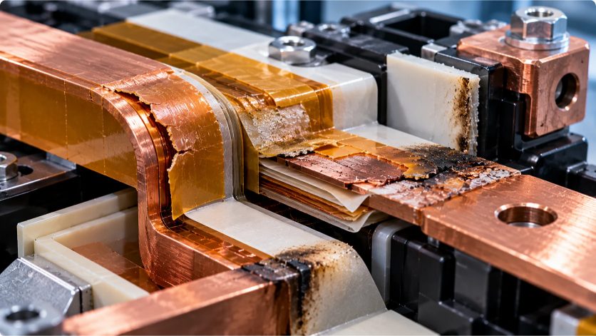
Electrical Breakdown
Electrical breakdown may result from excessive stress, defects, contamination or progressive degradation.
Prevention: Use appropriate insulation coordination, material qualification and representative assembly testing.
Partial Discharge Erosion
Repetitive discharge activity may damage vulnerable insulation interfaces.
Prevention: Review electrical waveform, geometry, air gaps and insulation-system design.
Thermal Aging
Long-term heat exposure can alter mechanical and electrical properties.
Prevention: Use grade-specific thermal endurance data and representative aging tests.
Cracking and Abrasion
Mechanical movement or installation damage can compromise film coverage.
Prevention: Review edge geometry, assembly stresses and vibration exposure.
Delamination
Multilayer or adhesive-backed materials may separate under thermal, chemical or mechanical stress.
Prevention: Test the complete construction with representative substrates and exposure conditions.
Moisture and Contamination
Moisture or conductive contamination may reduce insulation reliability.
Prevention: Define cleanliness, sealing and environmental qualification requirements.
Dimensional Instability
Shrinkage or movement can expose conductive features.
Prevention: Validate thermal dimensional behavior and installed tolerances.
9. Testing and Qualification Methods
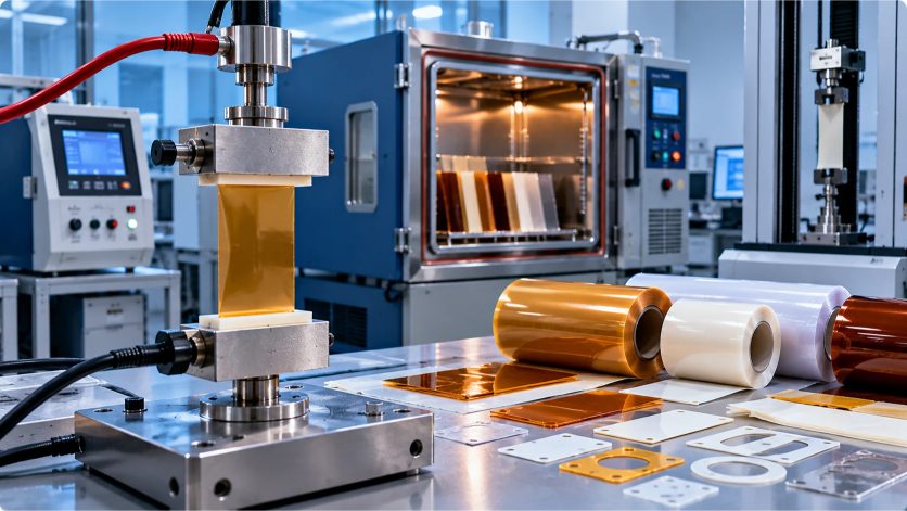
Material qualification should be linked to the actual electrical insulation function.
| Evaluation Area | Possible Tests or References | Purpose |
|---|---|---|
| Dielectric breakdown | ASTM D149; IEC 60243 series | Characterize breakdown behavior under defined conditions |
| Electrical resistivity | ASTM D257; IEC 60093 | Evaluate resistance or resistivity |
| Thermal endurance | IEC 60216 series | Evaluate thermal endurance characteristics |
| Insulation coordination | IEC 60664-1, where applicable | Establish relevant insulation coordination principles |
| Rotating-machine insulation | IEC 60034-18 series, where applicable | Evaluate rotating-machine insulation systems |
| Partial discharge | IEC 60270 and relevant application-specific methods | Characterize discharge activity |
| Mechanical durability | Appropriate tensile, tear, puncture and abrasion methods | Assess physical robustness |
| Environmental reliability | Project-specific thermal cycling, humidity and chemical tests | Evaluate service-related degradation |
These references do not all apply to every material or finished product.
The relevant editions, test conditions and acceptance criteria must be confirmed for the specific application.
Inverter Testing
Representative testing may need to include the actual switching waveform, busbar geometry, environmental conditions and installed insulation construction.
Motor Testing
Motor insulation should be evaluated as a system where required, including winding materials, impregnation and inverter-fed electrical stresses.
OBC Testing
Onboard charger qualification may involve dielectric withstand, insulation resistance, spacing, thermal behavior and safety requirements for the finished charger.
Material vs Component vs System Qualification
Material testing characterizes the film or laminate.
Component testing evaluates the converted insulation part in a representative geometry.
System testing evaluates the complete inverter, motor or charger under applicable requirements.
Passing one level does not automatically establish compliance at the others.
10. Design and Manufacturing Considerations
Film Thickness
Thickness must balance electrical requirements, mechanical protection, flexibility and packaging constraints.
Do not assume breakdown voltage scales linearly with thickness.
Die-Cut Geometry
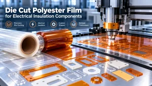
Custom parts may require holes, slots, radii and precise edge coverage.
Poor geometry can introduce local mechanical stress or leave conductive surfaces exposed.
Adhesive-Backed Insulation
Adhesive-backed films may simplify assembly.
However, the adhesive introduces additional thermal, chemical and aging considerations.
Rolls, Sheets and Die-Cut Parts
Rolls may be appropriate for continuous production and automated converting.
Sheets may suit prototypes or certain fabrication processes.
Die-cut parts can provide repeatable geometries for defined assemblies.
Process Cleanliness
Contamination, burrs and damaged edges may undermine insulation performance.
Inspection and handling requirements should be included in the specification.
For additional design guidance, see our Die-Cut Insulation Parts Design Guide.
11. Engineering Material Selection Workflow
A structured process can reduce the risk of selecting a material based on incomplete data.
Step 1: Identify the Application
Define whether the material is used in an inverter, motor or onboard charger.
Step 2: Define the Insulation Function
Determine whether the component provides electrical isolation, mechanical protection, thermal separation or a combination of functions.
Step 3: Establish Electrical Requirements
Document operating voltage, transient conditions, switching waveform and relevant insulation requirements.
Step 4: Define Thermal and Environmental Conditions
Specify continuous temperature, peak exposure, thermal cycling, moisture and chemical conditions.
Step 5: Review Geometry and Mechanical Loading
Provide drawings, bend requirements, edge conditions, thickness and tolerances.
Step 6: Compare Material Grades
Shortlist PI, PET, PEN, PTFE or suitable composite materials using verified grade-specific data.
Step 7: Prototype the Actual Component
Evaluate the material in the intended thickness, construction and geometry.
Step 8: Perform Representative Qualification
Test electrical, thermal, mechanical and environmental performance against the defined acceptance criteria.
Step 9: Confirm Production Requirements
Agree on material identification, dimensions, inspection, packaging, documentation and change control.
12. RFQ Checklist for EV Electrical Insulation Materials
Technical buyers can improve supplier communication by providing a clear application specification.
| RFQ Requirement | Information to Provide |
|---|---|
| Application | Inverter, motor or onboard charger |
| Component | Busbar barrier, slot liner, phase separator, transformer insulation, etc. |
| Material preference | PI, PET, PEN, PTFE or composite |
| Voltage conditions | Operating, peak, transient and waveform requirements |
| Temperature | Continuous, peak and thermal cycling profile |
| Thickness | Nominal thickness and tolerance |
| Electrical properties | Required tests and acceptance criteria |
| Mechanical requirements | Flexibility, puncture, abrasion, vibration |
| Chemical exposure | Cooling fluids, impregnation materials, cleaning agents |
| Adhesive | Adhesive-backed or non-adhesive; substrate details |
| Drawing | PDF, DXF or other controlled drawing |
| Supply format | Roll, sheet or die-cut part |
| Documentation | TDS, test reports and required declarations |
| Quantity | Prototype volume and estimated annual demand |
Where a specific certification, material grade or test report is mandatory, identify it explicitly during the RFQ process.
13. Electrical Insulation Film and Precision Converting Support
HighTemp Material focuses on high-temperature polymer films, electrical insulation materials and precision converting for industrial applications.
Relevant material categories include:
- Polyimide (PI) films
- PET insulation films
- PEN films
- PTFE films
- Selected high-temperature adhesive tapes
- Custom-cut electrical insulation components
Depending on the project, customers may require film rolls, sheets or precision die-cut parts.
Material grade availability, documentation and converting feasibility should be confirmed for each RFQ.
Request Technical Material Support
Are you developing an insulation component for an EV traction inverter, electric motor or onboard charger?
Share your application, operating voltage, temperature profile, preferred material, thickness, drawing, required testing and estimated quantity.
Contact HighTemp Material to discuss electrical insulation films and custom converting requirements.
Frequently Asked Questions
What insulation materials are used in EV traction inverters?
Depending on the component, engineers may consider PI, PET, PEN, PTFE, composite laminates and other specialized insulation systems. The exact choice depends on voltage stress, temperature, geometry and qualification requirements.
Is polyimide film suitable for inverter busbar insulation?
PI film may be considered for suitable busbar insulation constructions. However, the grade, thickness, electrical waveform, edge coverage and installed assembly must be qualified.
Which materials are used for electric motor slot insulation?
Motor slot insulation may use polymer films and composite laminates. The complete motor insulation system must satisfy electrical, thermal, mechanical and processing requirements.
Can PET film be used in EV motor insulation?
Certain PET grades may be suitable for selected motor insulation functions. Their use depends on the required thermal endurance, electrical performance and insulation-system qualification.
Why is partial discharge important in inverter-fed motors?
Fast-switching voltage waveforms and local electric fields can create conditions where partial discharge becomes relevant. Its significance depends on the winding construction and operating conditions.
What insulation is required in onboard charger transformers?
Transformer insulation depends on winding geometry, primary-secondary isolation requirements, temperature, voltage stress and applicable product standards. Films, tapes, bobbins and other insulation components may be used.
Is dielectric strength enough to select an EV insulation film?
No. Engineers must also evaluate temperature, mechanical durability, partial discharge behavior where applicable, environmental conditions and complete assembly performance.
What is the difference between PI and PET insulation films?
PI and PET differ in their material characteristics, cost and available grades. Selection should be based on verified properties under the actual application conditions.
Can custom die-cut insulation parts improve EV power electronics assembly?
They may simplify handling and provide repeatable geometries, but their dimensional accuracy, edge coverage and performance must be verified.
What information should be included in an EV insulation material RFQ?
Include the application, electrical waveform, voltage, temperature, material preference, thickness, drawing, qualification criteria, supply format and estimated quantity.
Conclusion
Electrical insulation is a critical design element in EV traction inverters, motors and onboard chargers.
Although PI, PET, PEN, PTFE and composite materials can all provide useful insulation functions, they are not interchangeable.
The appropriate selection depends on electrical stress, thermal exposure, mechanical conditions, installation geometry and the required qualification process.
For engineers and technical buyers, the most reliable approach is to define the application requirements first, compare verified material grades and validate the complete installed construction.
Contact HighTemp Material for electrical insulation film and custom converting discussions.
Engineering disclaimer: This guide provides general engineering information. It does not establish grade-specific temperature ratings, dielectric performance, UL recognition, motor insulation-system classification or EV component certification. All critical properties, documentation and supplier capabilities must be confirmed for the exact material and application.